PCX SMS AND PCX 256 SYSTEM MANUAL
Page: 132 RINS871-3
17.12.3 Terminals of the PCX-ROX16R
K+
RS-485 +12V Supply
NC#
PGM Relay Normally Closed Output
A
RS-485 ‘A’ Data
C#
PGM Relay Common Output
B
RS-485 ‘B’ Data
NO#
PGM Relay Normally Open Output
K–
RS-485 0V Supply
T T
Tamper Terminals
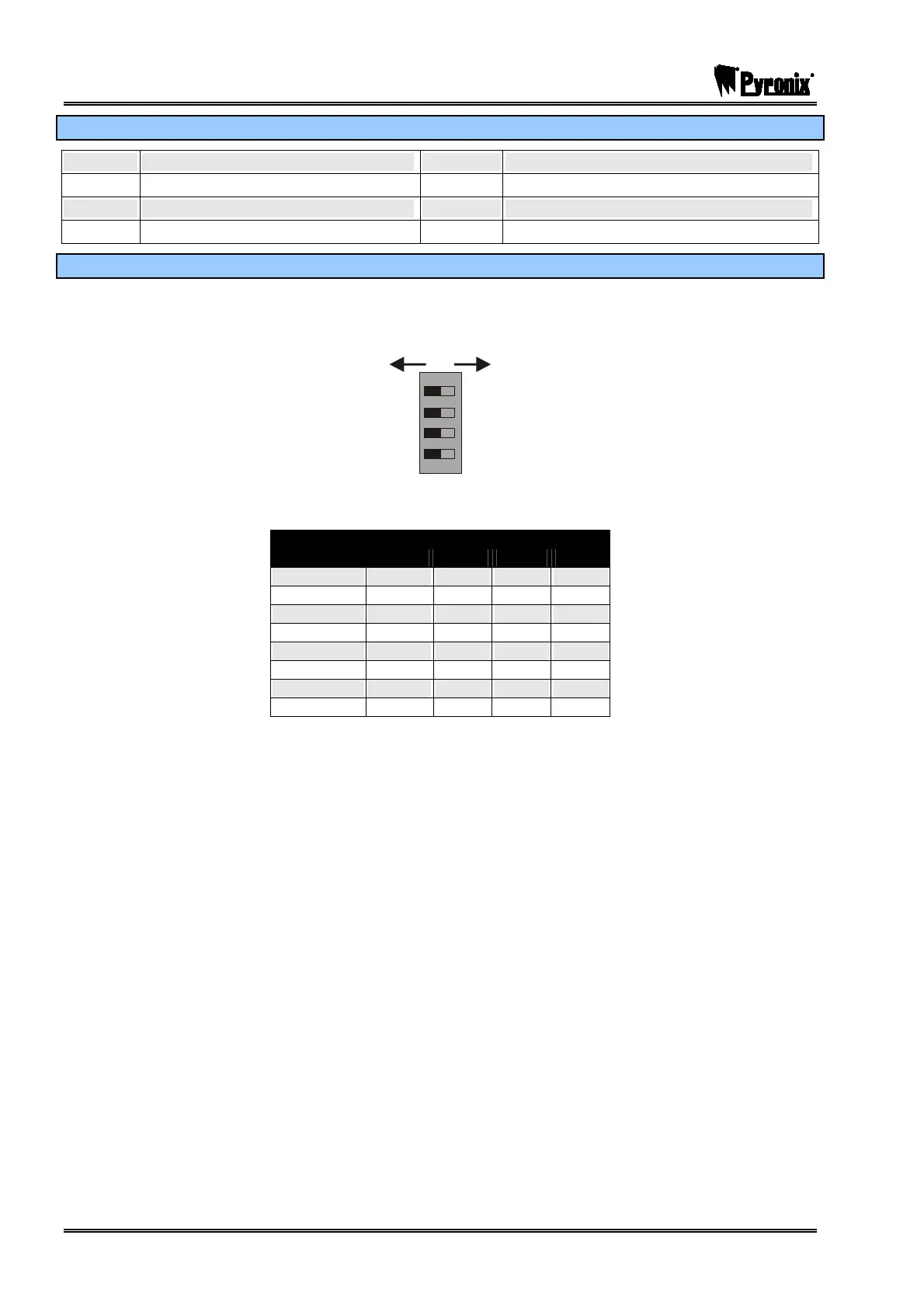
17.12.4 Addressing the PCX-ROX16R
ROXs are addressed using the DIP switches on the PCB. A maximum of 8 ROXs can be connected to a
PCX 256 system and 1 ROX to the PCX 26/SMS. The DIP switches operate as follows:
OFF ON
8
4
2
1
Switches should be On or Off as shown in the following table.
Switch
Address
1 2 4 8
00 OFF OFF OFF OFF
01 ON OFF OFF OFF
02 OFF ON OFF OFF
03 ON ON OFF OFF
04 OFF OFF ON OFF
05 ON OFF ON OFF
06 OFF ON ON OFF
07 ON ON ON OFF