PCX SMS AND PCX 256 SYSTEM MANUAL
RINS871-3 Page: 27
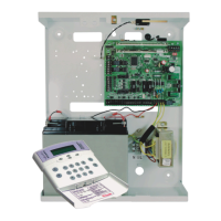
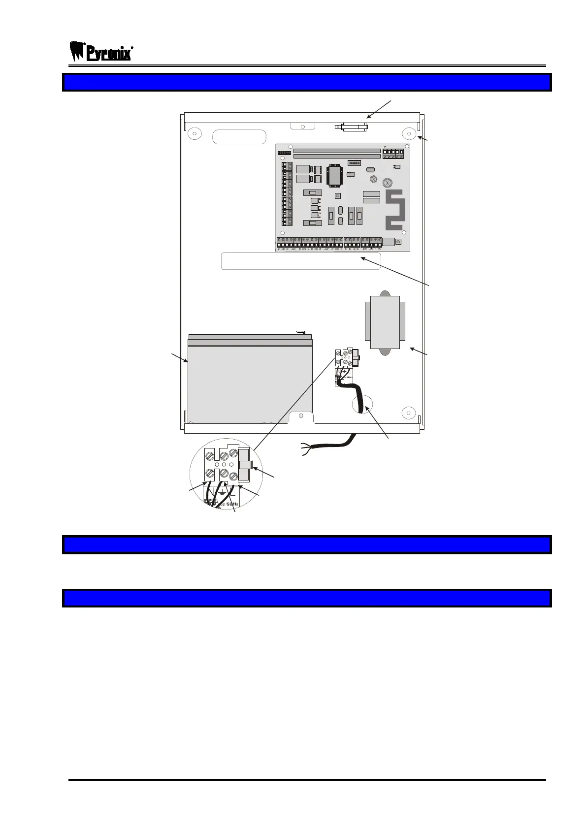
7.4 The PCX Panel Layout
T
A
M
P
E
R
NO1
DIGI MODEM CA RD SLOT
EXPANSION CARD SLOT
AUX+
C1
PGM3
NC1
PGM4
NO2
PGM5
T-1 R-1 TIP RING
C2
BT
NC2
B-
B+
F2
F3 F4 F5
F1
To Ma i n s Supp ly
Neutral
Live
Fuse carrier handle
(fuse nominal - 250mA)
Earth
Main Cable
Entry Hole
Battery
17Ah
Cable
Entry Holes
Wall Fixing
Holes
Tamp er Sw itc
Mains
Transformer
17Ah
7.5 Battery Installation Procedure
Place two foam pads on the bottom of the battery and two on the upper rear. Place the battery in the case
and secure with two tie wraps.
7.6 Mounting Procedure for Devices
Mount the equipment carefully in suitable locations, noting particularly the following:
a. Input expander units (RIXs or RIX2s) should be located to suit the wiring to appropriate detectors.
Mounting more than two together is not recommended.
b. Where input expanders, output modules or access controllers are mounted on power supplies, all
connections are automatically made to draw all current from the power supply, and to use the system
diagnostic capabilities to control the power supply.
c. Intelligent power supplies cannot be used in isolation from the PCX system plug-on PCBs.
d. Keypads and tag readers should NOT be mounted on or near a metal surface, or within a metre of each
other, or tag response could be affected.
e. Where provided, metal housings must have the earth strap connected to the lid to meet electrical safety
regulations.