PCX SMS AND PCX 256 SYSTEM MANUAL
RINS871-3 Page: 121
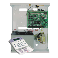
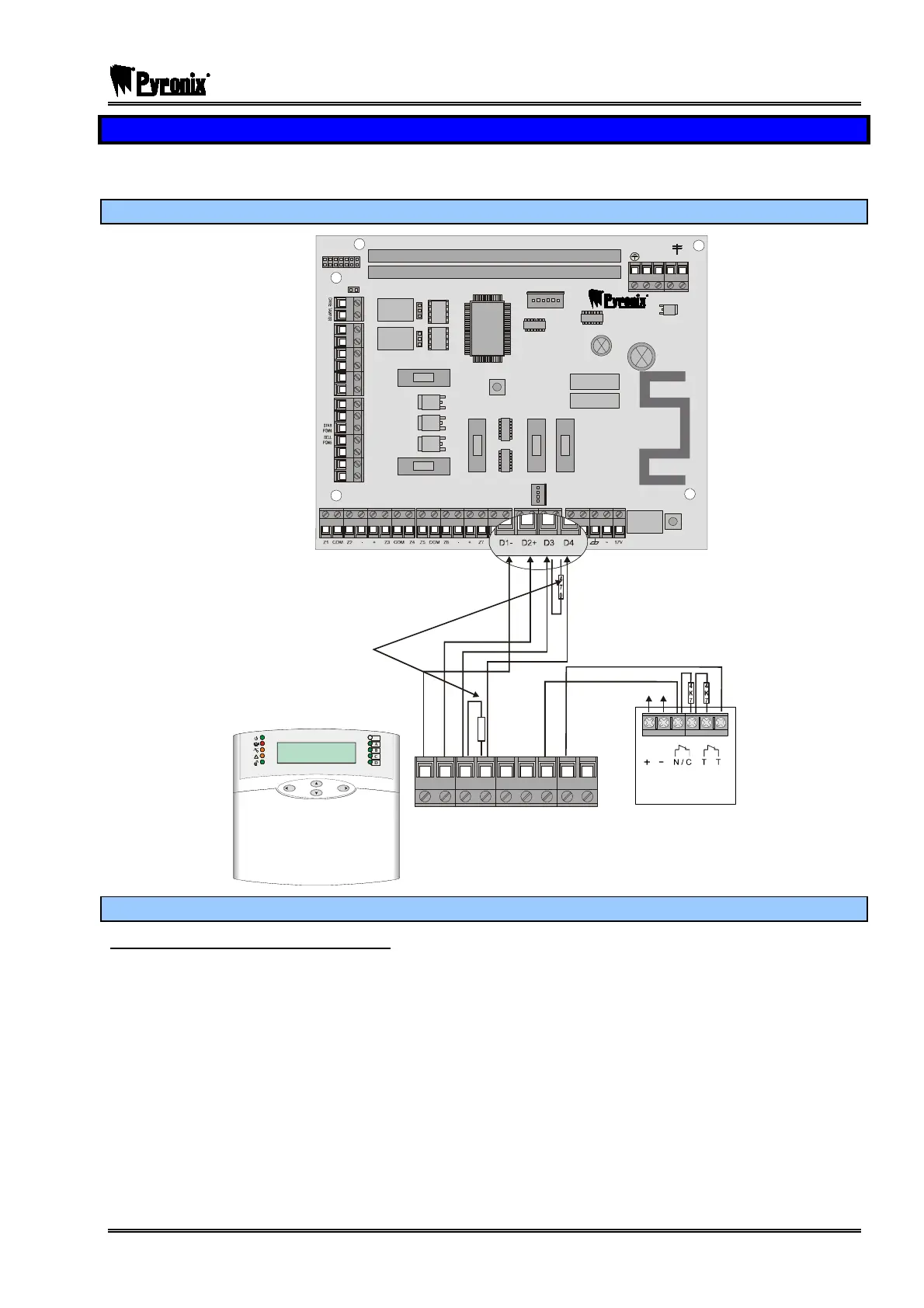
17.6 Keypads Wiring (PCX-LCD/UK)
A maximum of 4 keypads can be installed onto the PCX 26/SMS system and a maximum of 16 can be
installed on to the PCX 256 system.
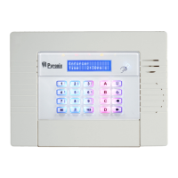
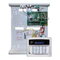
17.6.1 Connecting the PCX-LCD/UK
NC1
COMMS PGMS
TAM PE R
RESET
ENGINEER
KEYPAD
RS232
BATTERY
CONNECT
----------------SAB----------------
COMMUNICATION CARD
EXPANSION CARD SLOT
AUX+
C1
SPK
NO1
NC2
-1 B-1 A B
C2
TR
NO2
B-
B+
F2
F3 F4 F5
F1
PGMS
BELL
AUX
BUS
BATTERY
D4D1- D2+ D3 Z2 Aux+ Com Z1 PGM1
PYRONIX
Time 20:45 c
!!
D
C
B
A
4
0
7
470Ω Resistor
connected to
the control panel
and to the device
which is furthest
away
SUPPLY
ALARM TAMPER
+AUX-
Input
PIR
Detector
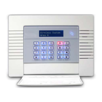
17.6.2 Addressing the PCX-LCD/UK
To Address The Keypads Individually.
¾ Press the p key.
¾ “Enter Your Code” will be displayed.
¾ Press and hold the p key.
¾ Until the display shows “ENTER CODE”
¾ Enter # and address the keypad as you wish.
¾ Press the Okey for additional options, or press the kkey to save the data.
Make sure that the keypad is addressed correctly – please see page: 60.
The keypad also has 2 inputs on board and an output that can be used. Please see page Error! Bookmark
not defined. to see how the inputs are addressed for each panel.