PCX SMS AND PCX 256 SYSTEM MANUAL
Page: 28 RINS871-3
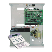
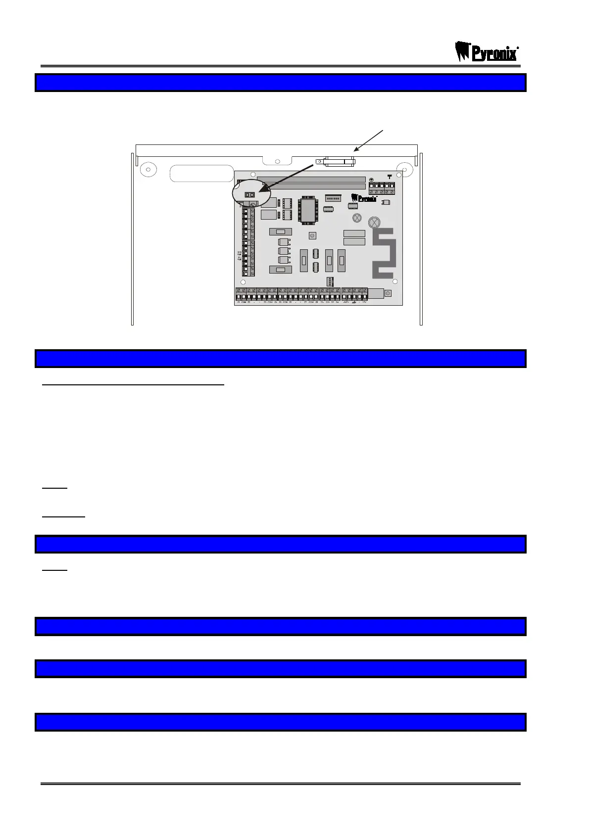
7.7 Tamper Switch
The Tamper switch that is already fitted onto the metal case connects via a plug-on connector to the tamper
pins on the PCX control panel as shown below:
Tamper Switch
NC 1
COMMS PGM S
TAMPE R
RESET
ENGINEER
KEYPAD
RS232
BATTERY
CO NNE CT
---- ---- --------S AB-- ---- ----- ---- -
COMMU NIC ATION CARD
EXPAN SION CARD SLOT
AUX+
C1
SPK
NO 1
NC2
-1 B-1 A B
C2
TR
NO 2
B-
B+
F2
F3 F4 F5
F1
PGMS
BELL
AUX
BUS
BATTERY
7.8 Mains Connection
MAINS ELECTRICITY IS DANGEROUS!
Mains connection must be performed by a qualified electrician, in accordance with electrical wiring
regulations (BS.7671).
The earth connection must be correctly made to the centre terminal of the mains block, and to terminal G1 of
the End Station, and of any intelligent power supplies.
Metal lids must be correctly connected to mains earth by the wiring loom provided, before securing in
position.
Note:
The PCB ground connection is NOT a safety earth connection, but is for EMC filtering
purposes.
Warning:
Always disconnect the mains supply before removing the cover and working on the
equipment.
7.9 System Connections
Note: Never add equipment to the system with power applied, or damage can result.
Please refer to the following diagrams to identify the functions of all the terminals on PCX components. Note
that all components use the same identification for equivalent applications – e.g. D1, D2, D3 and D4 will
always be the RS-485 terminations, etc.
7.10 Digi Modem Card
Information for installing the Digi Modem Card is shown separately on page 110.
7.11 Expander Card
Information for installing the Expander card is shown separately on page 112. Please note that this is not
available on the PCX 26/SMS.
7.12 Access Control and Guard Tour Equipment
Information for installing access control and guard tour equipment is shown in page: 138. Please note that
this is not available on the PCX 26/SMS.