PCX SMS AND PCX 256 SYSTEM MANUAL
RINS871-3 Page: 127
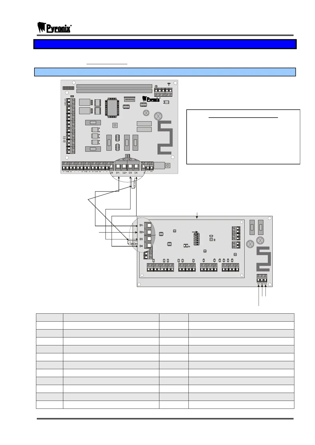
17.10 Remote Input Expander (PCX-RIX8+/PSU)
Every PCX-RIX8+ will come with its own power supply. Please note when connecting the RIX PSU, the
terminal “D2” should not be connected to the control panel.
17.10.1 Connecting the PCX-RIX8+/PSU
NC1
COMMS PGMS
TAM PE R
RESET
ENGINE ER
KEYPAD
RS232
BATTERY
CONNECT
------------ ----SAB----------------
COMMUNICATION CARD
EXPANSION CARD SLOT
AUX+
C1
SPK
NO1
NC2
A-1 B-1 A B
C2
TR
NO2
B-
B+
F2
F3 F4 F5
F1
PGMS
BELL
AUX
BUS
BATTERY
Earth
RIX Connects via 2 connectors.
AC
Input
Z1 Z3 Z5 Z7
E1-
D1-
D1-
E2+
D2+
D2+
E3
D3
D3
T
A
M
P
E
R
E4
D4
D4
COM COM COM COMZ2 Z4 Z6 Z8
PGM1
PGM2
PGM3
PGM4
TA MPE R
FAULT
32
16
8
4
2
1
DDR ESS
ON
-- -
++ ++
470Ω Resistor
connected to
the control panel
and to the device
which is furthest
away
THE D2 TERMINAL MUST
NOT BE CONNECTED TO
THE CONTROL PANEL
Power Supply
D1
RS-485 0V Supply
Z4
Input 4
D2
RS-485 +12V Supply
-
Auxiliary -0V Supply
D3
RS-485 ‘A’ Data
+
Auxiliary +12V Supply
D4
RS-485 ‘B’ Data
Z5
Input 5
Z1
Input 1
COM
Input Common
COM
Input Common
Z6
Input 6
Z2
Input 2
-
Auxiliary -0V Supply
-
Auxiliary -0V Supply
+
Auxiliary +12V Supply
+
Auxiliary +12V Supply
Z7
Input 7
Z3
Input 3
COM
Input Common
COM
Input Common
Z8
Input 8
PGMs
Programmable Outputs
TAMPER
Tamper Inputs
Power Supply Specification
Power Supply: 1.5A
Mains: 220-240V AC 50Hz 150mA
Mains Fuse: Slow Blow (T) = 250mA
Output: 13.75V 1.0A Continuous
Battery Fuse: 3.15A Quick Blow
Output Fuse: 1.25A Quick Blow