PCX SMS AND PCX 256 SYSTEM MANUAL
Page: 122 RINS871-3
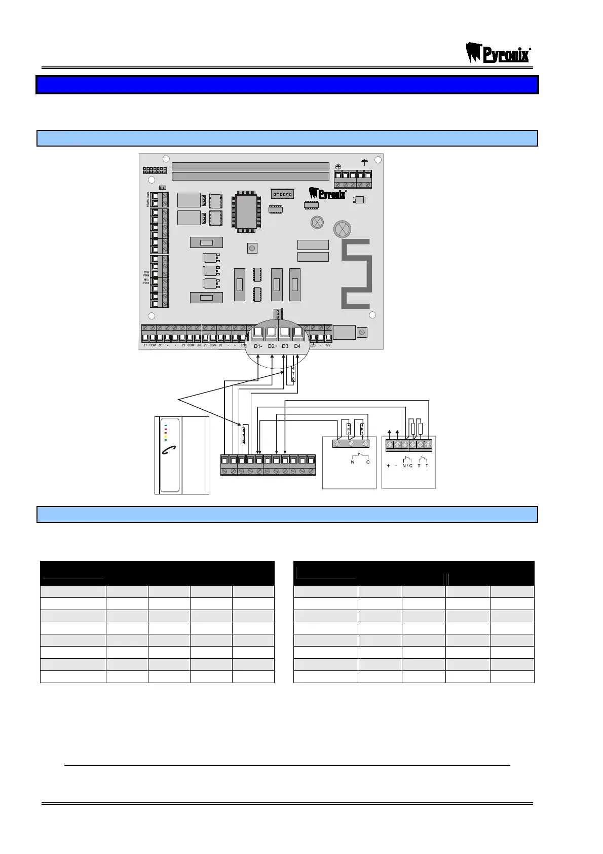
17.7 Tag Reader Wiring (PCX-PROX/INT)
A maximum of 3 internal tag readers can be installed onto the PCX 26/SMS system and a maximum of 15
can be installed onto the PCX 256 system.
17.7.1 Connecting the PCX-PROX/INT
NC1
COMMS PG MS
TAMP ER
RESET
ENGINEER
KEYPAD
RS232
BATTERY
CONNECT
----------------SAB----------------
COMM UNICATION CARD
EXPANSION CARD SLOT
AUX+
C1
SPK
NO1
NC2
-1 B-1 A B
C2
TR
NO2
B-
B+
F2
F3 F4 F5
F1
PGMS
BELL
AUX
BUS
BATTERY
Power
Alarm
Ta mp e r
Fau lt
Unset
Tag
470Ω Resistor
connected to
the control panel
and to the device
which is furthest
away
4
K
7
4
7
K
+AUX-
SUPPLY
ALARM TAMPER
Spare
LARM
Input 2
Input 1
D1 D2 D3 D4 K1 K2 K3 K4 L1 L2 L3
PIR
Detector
PIR
Detector
17.7.2 Addressing the PCX-PROX/INT
NOTE: Tag Readers are addressed using the address selection switches on the PCB. Open
the links to add up to the address as shown in the following table.
Switch
Switch
Address
1 2 4 8
Address
1 2 4 8
00* C C C C 08 C C C O
01 O C C C 09 O C C O
02 C O C C 10 C O C O
03 O O C C 11 O O C O
04 C C O C 12 C C O O
05 O C O C 13 O C O O
06 C O O C 14 C O O O
07 O O O C 15 O O O O
C = Switch Closed O = Switch Open
Make sure that the reader is addressed correctly – please see page: 60.
The reader also has 2 inputs on board and an output that can be used. Please see page Error! Bookmark
not defined. to see how the inputs are addressed for each panel.
Please note a PCX-RIX2 will connect the same way and needs to be programmed as ‘Reader’