PCX SMS AND PCX 256 SYSTEM MANUAL
RINS871-3 Page: 139
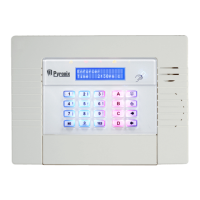
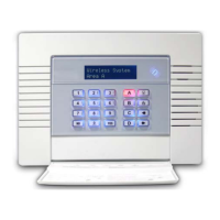
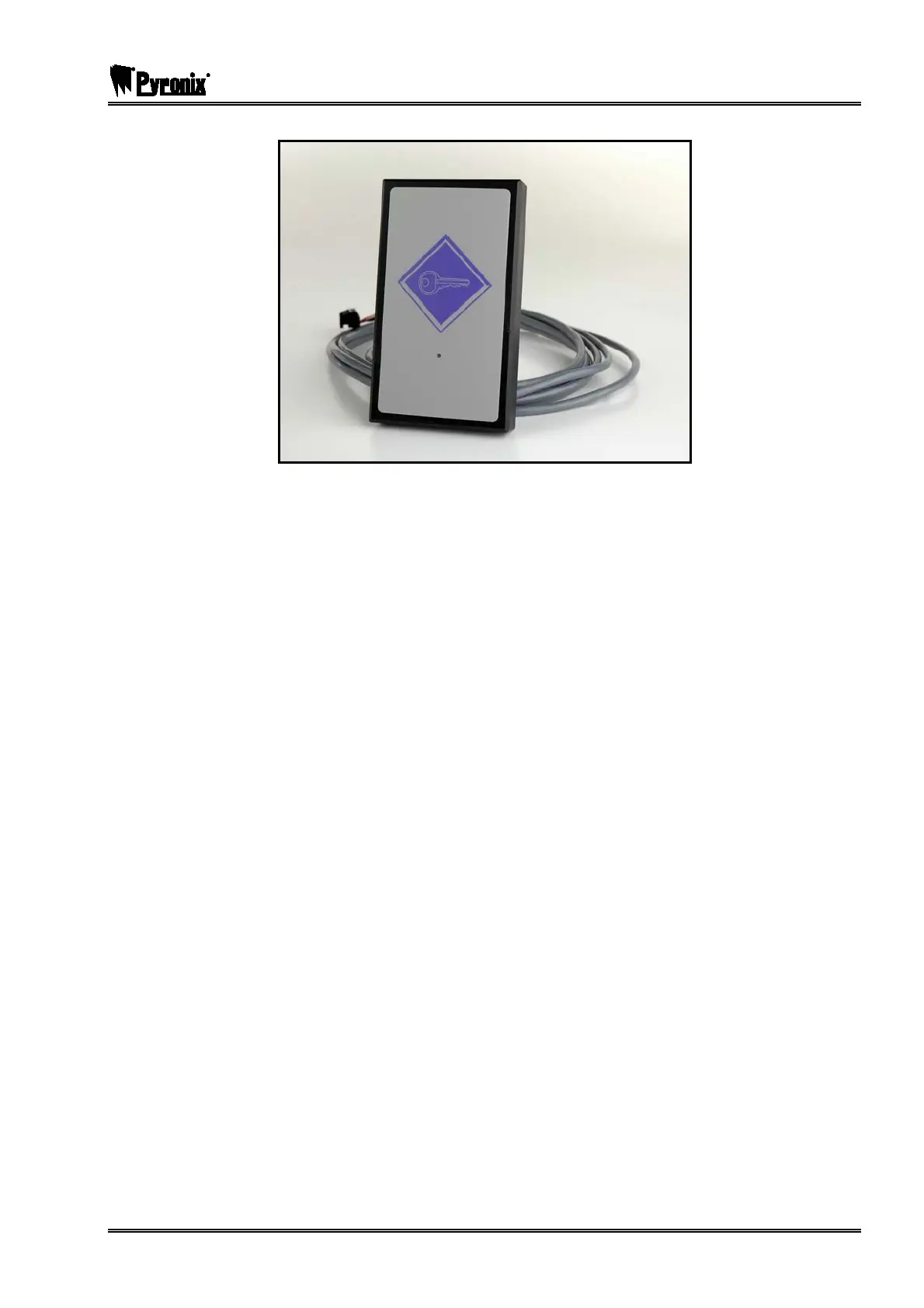
The Access Control Reader looks like the following:
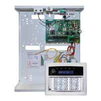
NOTE 1: Before powering up, the Door Station must be addressed using the coding
switches – open switches to add up to the address required.
NOTE 2: Issue 2 PCB is shown. Issue 1 Door Station PCBs do not have the full range of
options, nor provide full diagnostic features.
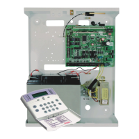
All connections to the intelligent power supply are automatically made to power the unit and lock mechanism
from the local power supply, and use the system diagnostic capabilities to control the power supply.
NOTE: In default mode, the Door Station communications section is powered from the local
power supply, through the plug-on connections. Do NOT, therefore, connect terminal D2 to
the RS-485 network.
Before powering up, the Door Station must be address using the coding switches as described further on in
this manual.