RED RAVEN OPERATION GUIDE
COPYRIGHT © 2016 RED.COM, INC 955-0127_V6.3, REV-E | 179
SERIAL (RS232 CONTROL)
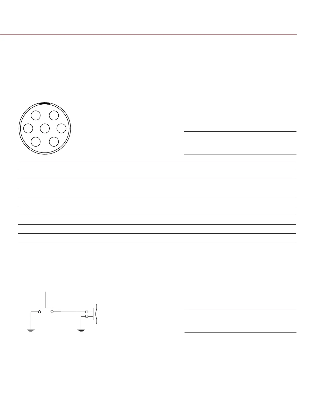
The DSMC2 REDVOLT Expander features a SERIAL connector. The 7-pin 0B LEMO SERIAL connector supports
RS232 RX, RS232 TX, and a General Purpose Input (GPI) trigger (active-low switch closure). The connector
also offers auxiliary power out, with a maximum sustained current draw of 1.5A.
To operate the GPI contact closure style trigger, short Pin 7 (GPI) to Pin 6 (ground).
The SERIAL connector was designed to support 6-pin 0B cables used with the RED Tactical Hand Controller
(T.H.C.). Although the connectors on those cables do not have pin 7 (GPI), the other 6 pins do match pins 1
to 6 on the SERIAL connector.
6 1
4 3
25
7
SERIAL CONNECTOR
PIN SIGNAL DESCRIPTION DIRECTION
1 GND Camera ground N/A
2 RS232 RX RS232 RX In
3 RS232 TX RS232 TX Out
4 AUX OUT +11.5 to +17 VDC unregulated battery pass-through power Out
5 N/A No connection (NC) N/A
6 GND Camera ground N/A
7 GPI General Purpose In (GPI) trigger (active-low switch closure) In
NOTE: Mating connectors are FHG.0B.307.CLAD (right-angle) or FGG.0B.307.CLAD (straight).
CONTACT CLOSURE STYLE TRIGGER BUTTON CIRCUIT (SERIAL)
The diagram below shows the contact closure style trigger button circuit on the SERIAL connector.
Momentary Action
Push Button
SERIAL
Pin 7
Pin 6
COMPATIBLE CABLES
For GPI applications, you can use this cable:
790-0553: RED 7-Pin 0B LEMO-to-Flying Lead Serial Port Cable (6')
For non-GPI applications, you can use this 6-pin cable:
790-0444: REDLINK®-to-T.H.C. Connector Cable 3'
Front Face of the SERIAL (RS232)
Connector (Looking at the Camera)
Contact Closure Style Trigger
Button Circuit Diagram (SERIAL)
 Loading...