The StandStill function block monitors the speed of a
device, causing a transition from 0 (FALSE) to 1 (TRUE) of
the ZERO output when the speed is lower than a selected
value.
Parameters
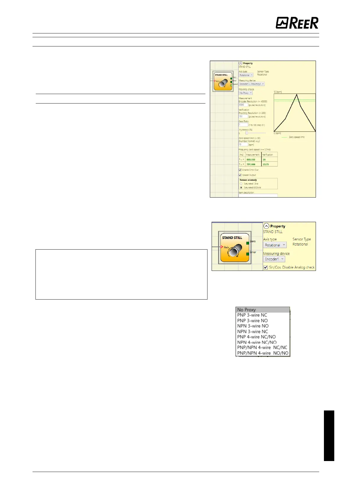
Axis type: It defines the type of axis controlled by the
device. It will be Linear in the case of a translation and will
be rotational in the case of motion around an axis.
Sensor Type: When that the previous parameter is Linear,
the Sensor Type defines the type of sensor connected to
the module inputs. It can be rotational (e.g. shaft encoder)
or Linear (e.g. optical array). This choice allows to define
the following parameters.
Measuring device: It defines the type of sensor(s) used.
The possible choices are:
- Encoder
- Proximity
- Encoder+Proximity
- Proximity1+ Proximity2
- Encoder1+ Encoder2
Sin/Cos: Disable Analog check: only when a Sin/Cos
Module is used, it is possible to disable the analog
verification sin
2
θ + cos
2
θ, carrying out a simplified
plausibility check of the Encoder signals.
When analogue control is disabled, the diagnostic
coverage decreases.
In addition, the safety level of the project drops from:
SIL 3->SIL 2 / PL e->PL d. Please refer to chapter
"Important safety instructions".
Pitch: If the Axis Type chosen was linear and rotational,
this field allows you to enter the sensor pitch to obtain a
conversion between sensor revolutions and distance
travelled.
Proximity choice: It allows you to choose the type of
proximity sensor from PNP, NPN, Normally Open (NA) and
Normally Closed (NC), with 3 or 4 wires.
(In order to ensure a Performance Level = PLe use a
proximity switch type PNP NO: ref. “Interleaved proximity -
> page 25).

 Loading...


