The StandStill and Speed Control function block monitors
the speed of a device, causing the transition from 0 (FALSE)
to 1 (TRUE) of the ZERO output when the speed is lower than
a selected output. In addition a transition from 0 (FALSE) to
1 (TRUE) of the OVER output is generated when the measured
speed exceeds a predetermined threshold.
Parameters
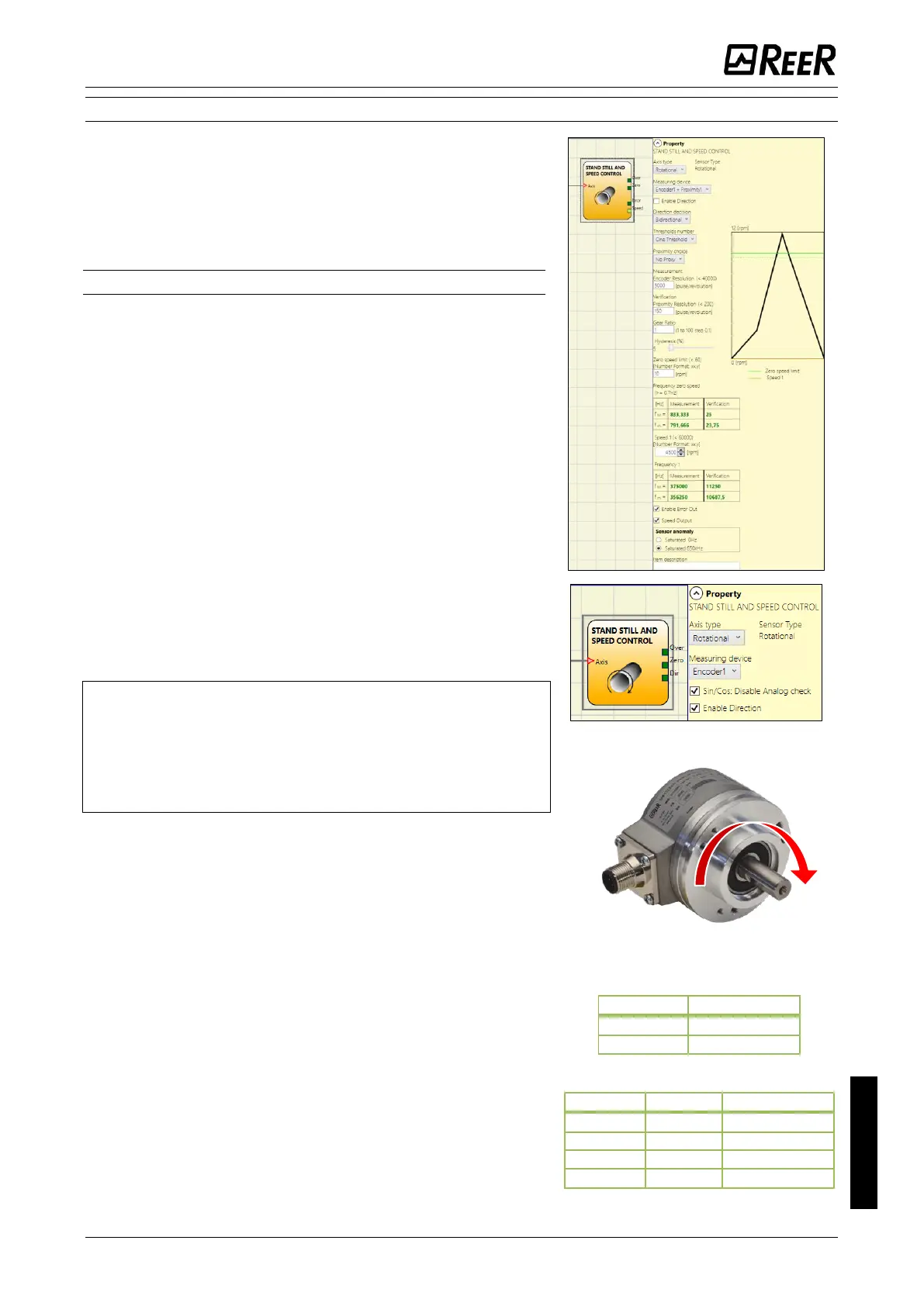
Axis type: It defines the type of axis controlled by the device.
It will be Linear in the case of a translation and will be
rotational in the case of motion around an axis.
Sensor Type: In the event that the previous parameter is
Linear, the Sensor Type defines the type of sensor connected
to the module inputs. It can be rotational (e.g. shaft encoder)
or Linear (e.g. optical array). This choice allows to define the
following parameters.
Measuring device: It defines the type of sensor(s) used. The
possible choices are:
- Encoder
- Proximity
- Encoder+Proximity
- Proximity1+ Proximity2
- Encoder1+ Encoder2
Sin/Cos: Disable Analog check: only when a Sin/Cos
Encoder is used, it is possible to disable the analog
verification sin
2
θ + cos
2
θ, carrying out a simplified plausibility
check of the Encoder signals.
When analogue control is disabled, the diagnostic
coverage decreases.
In addition, the safety level of the project drops from:
SIL 3->SIL 2 / PL e->PL d. Please refer to chapter
"Important safety instructions".
Enable direction: (Available only when at least one Encoder
input is present): when checked, the DIR output is enabled on
the function block. This output will be 1 (TRUE) when the axis
rotates Counterclockwise and will be 0 (FALSE) when the axis
rotates Clockwise.
Direction decision: It defines the direction of rotation for
which the set thresholds are made active. The possible
choices are:
- Bidirectional
- Clockwise
- Counterclockwise
If Bidirectional is selected, the excess of the set threshold is
detected whether the axis rotates clockwise or
counterclockwise. Selecting Clockwise or Counterclockwise,
this is detected only when the axis rotates in the selected
direction.

 Loading...


