MODULAR SAFETY INTEGRATED CONTROLLER MOSAIC
50 8540780 • 25/01/2023 • Rev.43
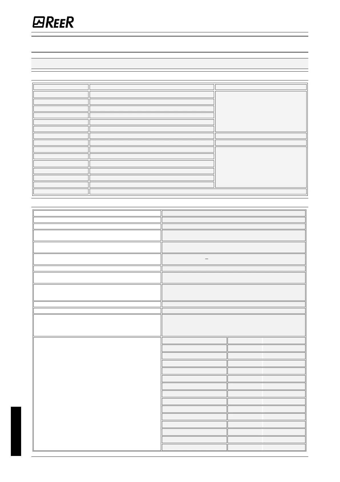
TECHNICAL FEATURES
GENERAL SYSTEM CHARACTERISTICS
Safety level parameters
See the technical data tables for each module
See the technical data tables for each module
EN ISO 13849-1:2015
EN 62061:2021
Max number of OSSD outputs
16 (MOSAIC M1); 32 (MOSAIC M1S, MOSAIC M1S COM)
Max number of signalling outputs
32 (MOSAIC M1); 48 (MOSAIC M1S, MOSAIC M1S COM)
Max number of slave units
(excluding MR2-MR4, MR8)
Max number of slave units of the same type
(excluding MR2-MR4-MR8)
24VDC + 20% / PELV, Protective Class III;
UL: Supply from class 2 (LVLE)
PNP active high (EN 61131-2) –
Max. applicable resistance 1,2kΩ
OSSD
(MOSAIC M1, MOSAIC M1S, MOSAIC M1S COM,
MI8O2, MI8O4, MO2, MO4, MO4L)
PNP active high - 400mA@24VDC max (each OSSD)
PNP active high - 2A@24VDC max (each OSSD)
Relays OUTPUTS (MR2, MR4, MR8, MOR4, MOR4S8)
6A max@240Vac max (each relais)
SIL1/PL C output
(MOSAIC M1, MOSAIC M1S, MOSAIC M1S COM,
MI8O2, MI8O4, MO2, MO4, MO4L, MOR4S8,
MO4LHCS8, MOS8, MOS16)
PNP active high - 100mA@24VDC max
Response time MOSAIC M1 (ms)
This response times depends on the following
parameters:
1) Number of Slave modules installed
2) Number of Operators
3) Number of OSSD outputs
For the right response time refer to the one calculated
by the DSD software (see Project report)
Failure Response time MOSAIC M1 (ms)
This parameter corresponds to the response time,
with the exception of MV modules with
Encoder/Proximity interface where is 2s

 Loading...


