Threshold number: It allows you to enter the number of thresholds for the maximum value of speed.
Changing this value will increase/decrease the number of thresholds that can be entered from:
• 1 to 8 with MOSAIC M1 fw >= 4.0, MOSAIC M1S fw >=5.1 and MVx fw >= 2.0, with
MOSAIC M1S COM and MVx fw >= 2.0
• 1 to 4 with MOSAIC M1 fw <4.0 or MOSAIC M1S< 5.1 or MVx fw < 2.0.
In the case of thresholds greater than 1, the input pins for the selection of the specific threshold will
appear in the lower part of the function block. Let the user to choose which threshold has to be
enabled.
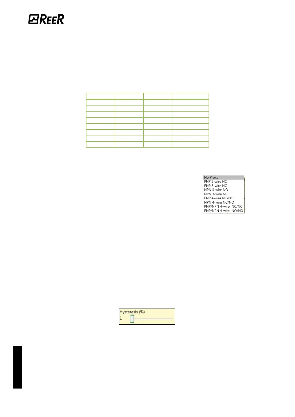
Proximity choice: It allows you to choose the type of proximity
sensor from PNP, NPN, Normally Open (NA) and Normally Closed
(NC), with 3 or 4 wires.
(In order to ensure a Performance Level = PLe use a proximity
switch type PNP NO: ref. “Interleaved proximity -> page 40).
Measurement: Enter in this field the number of pulses/revolution (in the case of rotational sensor)
or µm/pulse (linear sensor) relating to the sensor used.
Verification: Enter in this field the number of pulses/revolution (in the case of rotational sensor)
or µm/pulse (linear sensor) relating to the second sensor used.
Gear Ratio: This parameter is active if there are two sensors on the selected axis. This parameter
allows you to enter the ratio between the two sensors. If both sensors are on the same moving
parts, the ratio will be 1 otherwise the number corresponding to the report must be entered. E.g.
there are an encoder and a proximity switch, and the latter is on a moving part that (due to a gear
reduction ratio) rotates at twice the speed of the encoder. Therefore, this value must be set at 2.
Hysteresis (%): It represents the percentage hysteresis (the percentage is calculated from the
threshold value) below which the speed change is filtered.
Zero speed limit:
Enter in this field the maximum speed value above which the output of the function block (ZERO)
will be 0 (FALSE). If the measured speed is less than the set value, the output (ZERO) of the function
block will be 1 (TRUE).
Speed 1…8: Enter in this field the maximum speed value above which the function block output
(OVER) will be 0 (FALSE). If the measured speed is less than the set value, the function block output
(OVER) will be 1 (TRUE). The speed value could be entered with the decimal point provided that
MOSAIC M1 fw >= 4.0 or MOSAIC M1S fw >= 5.1 or MOSAIC M1S COM and MVx fw >= 2.0 were
used.

 Loading...


