37
SS and SS-L Models
USER GUIDE
INSTALLATION
SMART-SENSOR
™
2004 – 2014 Reliable Controls
®
Corporation. All rights reserved.
2
Mount the backplate to the wall. Ensure that the SMART-Net
™
cable passes
freely through the provided large square opening prior to securing the
backplate.
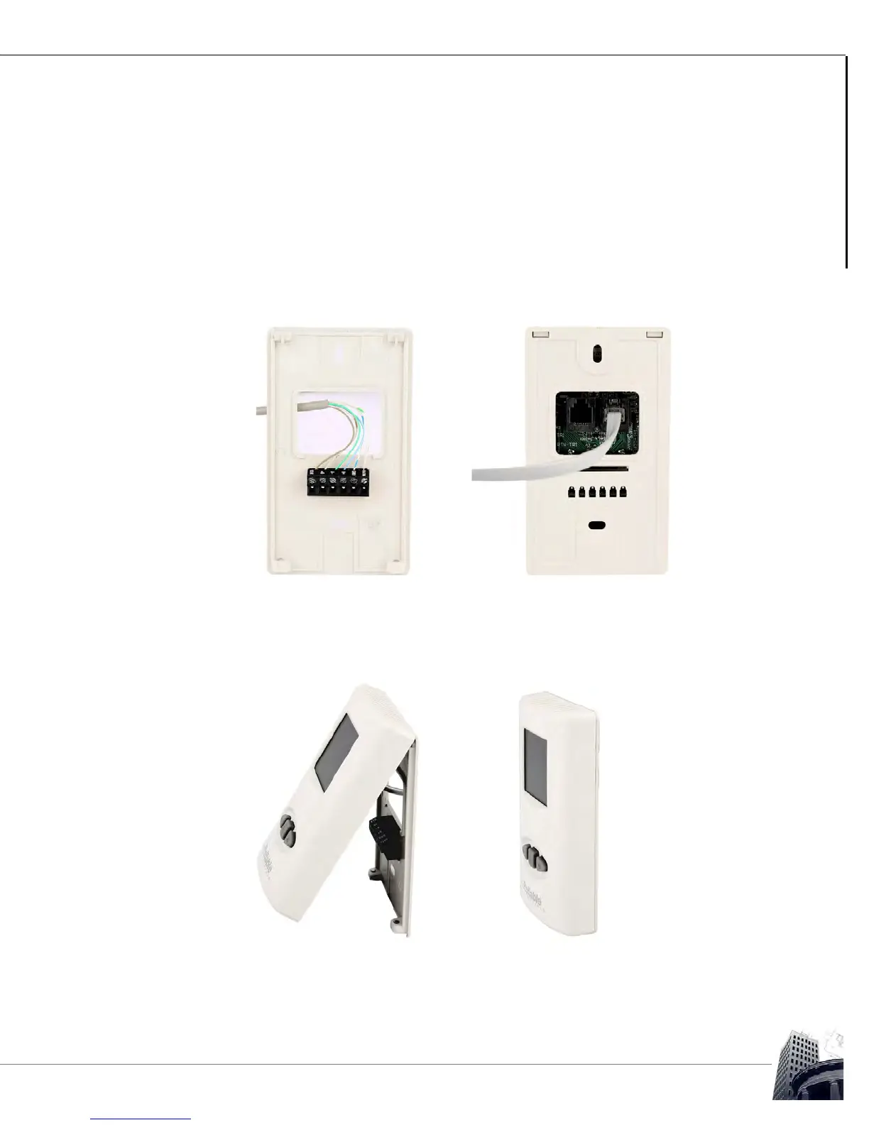
TO TERMINATE THE CABLING AND REASSEMBLE THE SS
1
Terminate the SMART-Net
™
communication cable conductors to the SMART-
Sensor
™
using either the 6-pole terminal strip on the backplate or by crimping an
RJ11 connector and plugging it into either of the onboard RJ11 sockets on the
back of the SS.
FIGURE 30: SS TERMINATION METHODS
2 Install the sensor head to the backplate by placing the top of the SS into the
retaining clips on the top of the backplate, and then slowly and firmly bring the
SS down onto the backplate.
FIGURE 31: SS SENSOR INSTALLATION (SS-L PICTURED)
3 Finally, secure the SS by loosening (counter-clockwise) the Allen screws located
at the bottom of the sensor.