67
Outputs
USER GUIDE
INPUT/OUTPUT POINT OPTION (-IO)
SMART-SENSOR
™
2004 – 2014 Reliable Controls
®
Corporation. All rights reserved.
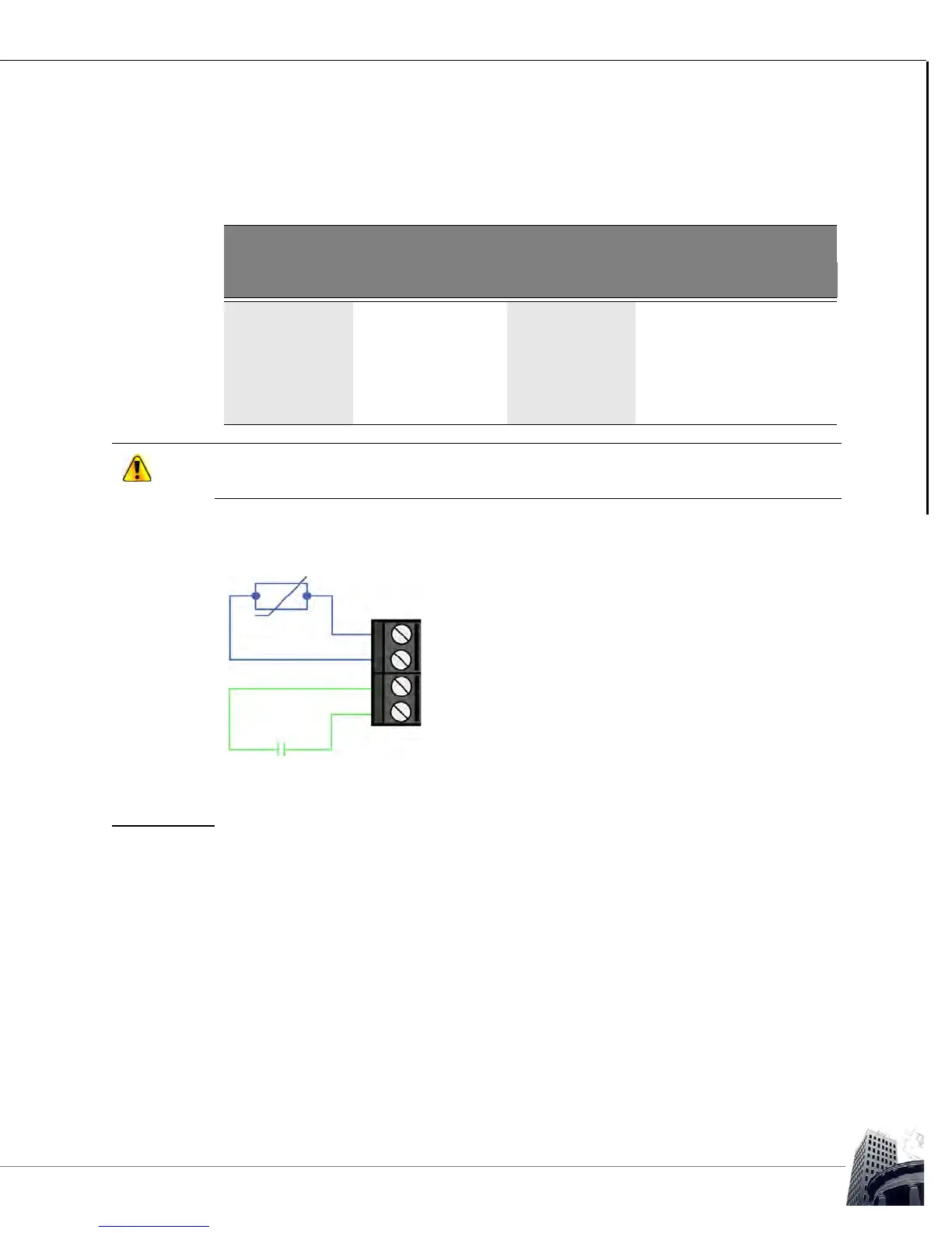
There is no hardware configuration necessary to define the inputs of an SS-IO. The
software configuration necessary to define each input is programmed in the SMART-
Sensor worksheet and detailed in Table 15.
SS-IO inputs terminate consistent with all MACH series dry-contact/10k thermistor inputs
as detailed in the figure below.
FIGURE 64: SS-IO INPUT WIRING
OUTPUTS
Field devices wire directly to the output terminal block on the SS-IO. A variable must be
created in the host controller to store a value corresponding to each output. The variables
that represent the outputs are then referenced using row 9 and row 10 of the SMART-
Sensor worksheet. To permit an operator to change the values of outputs 9 and 10
through the SS-IO interface, the User Edit column must be set to a value of Can Change.
TABLE 15: SS-IO INPUT PROGRAMMING DETAIL
Physical Characteristics SS Worksheet Configuration
Input Type Row Type Range
Input 1 Dry contact Row 7 State Off/On
10 k Thermistor Row 7 Analog °C or °F
Input 2 Dry contact Row 8 State Off/On
10 k Thermistor Row 8 Analog °C or °F
SS-IO models use a 10 k pull-up resistor against a 2.5 VDC reference voltage unlike the
traditional +5 V used for the auxiliary inputs.
Dry Contact
10k Thermistor
IN 1+
IN 1-
IN 2+
IN 2-