100
2004 – 2014 Reliable Controls
®
Corporation. All rights reserved.
SS-L PROGRAMMING EXAMPLE
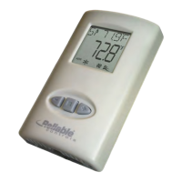
After the SMART-Sensor
™
LCD (SS-L) has been installed according to the instructions out-
lined in this manual, and is functional, the SS-L should be configured to provide the de-
sired operator interface and system status display.
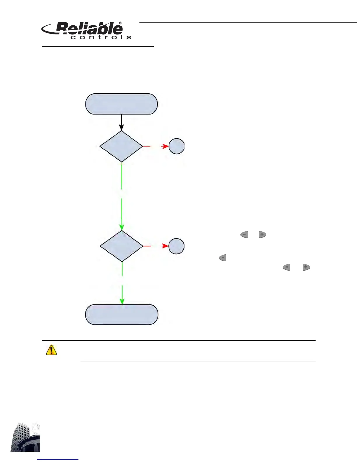
FIGURE 92: SS-L INSTALLATION FLOW CHART
Do not skip addresses or exceed the maximum number of supported SS-Ls based upon
the host controller.
Ensure that the SS-L has been installed according to the
installation guidelines in this manual.
When initially connected to the SMART-Net
™
or powered-up,
the SS-L displays all LCD segments for two seconds, followed
by the SS-L address for an additional two seconds, and finally,
the firmware version of the SS-L for one second.
All SS-Ls ship with a default SMART-Net
™
address of 1.
T
O CHANGE THE ADDRESS
1
Press and hold the and buttons for five sec-
onds.
2
Release for two seconds.
3
Press the button.
4
When SSADDR is displayed, use the and
buttons to select the desired address from 1 to 16.
SMART-Sensor
™
LCD
New Installation
Installation
Complete
Correct
Address
Program SSL using
RC-Studio
®
2.0
A
B
YES
YES
NO
NO