42
2004 – 2014 Reliable Controls
®
Corporation. All rights reserved.
WIRING FROM CONTROLLER TO SS
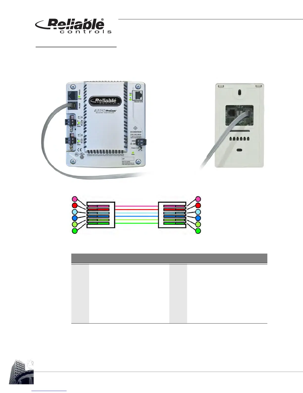
If the connection between the controller and the first SMART-Sensor
™
is completed using
an RJ11 crimp at each end, a rollover Voice Cable (SS-VC) is used to connect the host
controller to the first SS’s RJ11 jack on the SMART-Net
™
.
FIGURE 37: VOICE CABLE FROM HOST CONTROLLER TO FIRST SS
F
IGURE 38: RJ11 PIN-OUT BETWEEN CONTROLLER AND FIRST SS USING A ROLLOVER CABLE
If a controller’s SMART-Net
™
terminal block is used, the wiring connections should match
point to point. For example, the Clock connector on the controller should be connected to
the Clock connector on the SS’s terminal block, the Data to Data, and so forth.
TABLE 6: VOICE CABLE (SS-VC) ROLLOVER CABLE PIN-OUT
Controller
SMART-Sensor
™
LCD
1 Clock 6 Clock
2 +5 VDC 5 +5 VDC
3 A 4 A
4 B 3 B
5 GND 2 GND
6 Data 1 Data
6
5
4
3
2
1
6
5
4
3
2
1
Controller’s RJ11 SS’s RJ11