49
Operator Interface for the SS
USER GUIDE
OPERATOR INTERFACE
SMART-SENSOR
™
2004 – 2014 Reliable Controls
®
Corporation. All rights reserved.
OPERATOR INTERFACE
O
PERATOR INTERFACE FOR THE SS
SETPOINT ADJUSTMENT OPTIONS
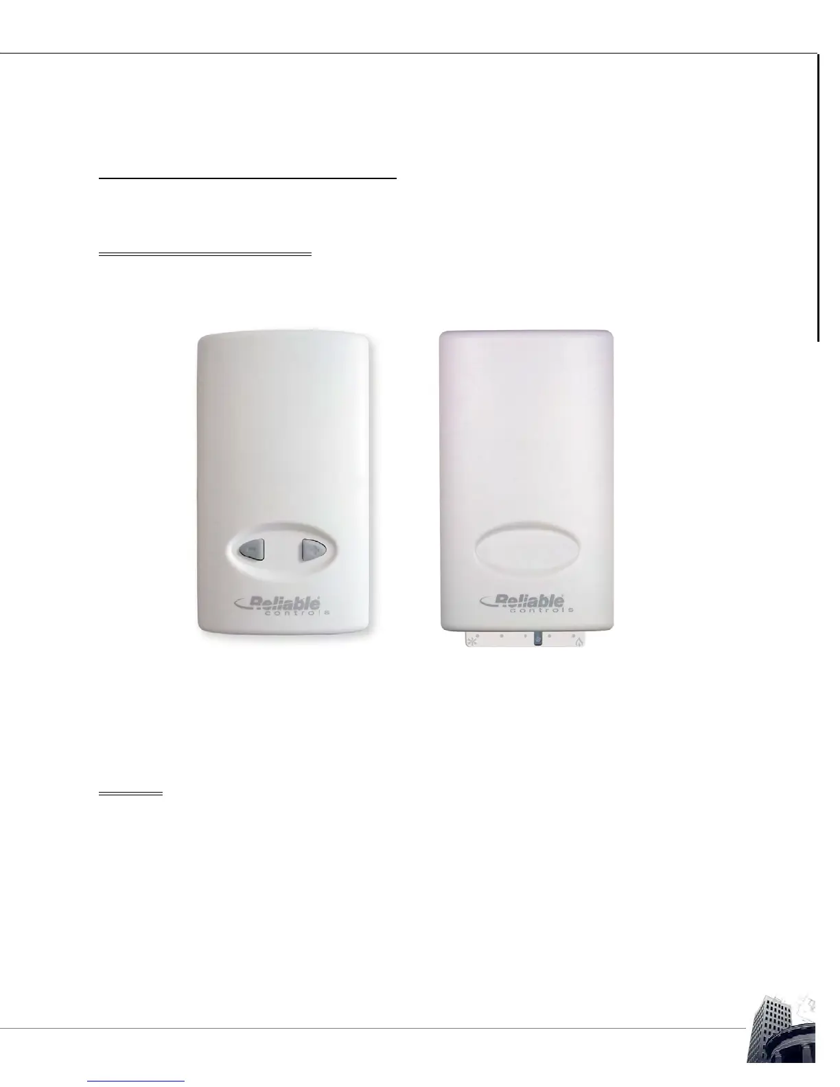
SS models can be ordered with optional Up/Down arrows (-UD) or the Slider (-S). These
options are typically used to control the temperature setpoint.
FIGURE 47: OPTIONAL UP/DOWN BUTTONS OR SLIDER ON AN SS
For SS models with the -UD or -S option, the buttons or slider affect point #2 on the
SMART-Sensor worksheet, called the Quick-adjust point. Moving the slider or pressing
the buttons will adjust the value of the Quick-adjust point, typically a setpoint.
TEST LED
SS models without the LCD screen have a Test LED located at the bottom of the circuit
board next to the onboard temperature sensor. The Test LED is used to prove wiring
integrity. After powering up the controller, the light is used to display test results. If
sufficient DC voltage is available (3.4 VDC), the light is enabled. If sufficient voltage is not
available, the light will remain off. If sufficient voltage is available and SMART-Net
™
communication is detected, the light will flash 8 times per second, for at least 2 minutes. If
sufficient voltage is available, but the SS cannot detect SMART-Net
™
communications, the
light will stay on solid until power is cycled. To re-initiate the test, disconnect and
reconnect SMART-Net
™
.