33
SS and SS-L Models
USER GUIDE
INSTALLATION
SMART-SENSOR
™
2004 – 2014 Reliable Controls
®
Corporation. All rights reserved.
INSTALLATION PROCEDURE
The installation of the SS requires four sequential procedures: the pre-installation cable
check, product disassembly, mounting, and cable connection and reassembly.
TO PERFORM A PRE-INSTALLATION CABLE CHECK
1
For SMART-Net
™
communication wiring, 24–26 AWG (0.25–0.14 mm
2
) solid or
26–28 AWG (0.14–0.08 mm
2
) stranded 6-conductor cable is recommended.
2
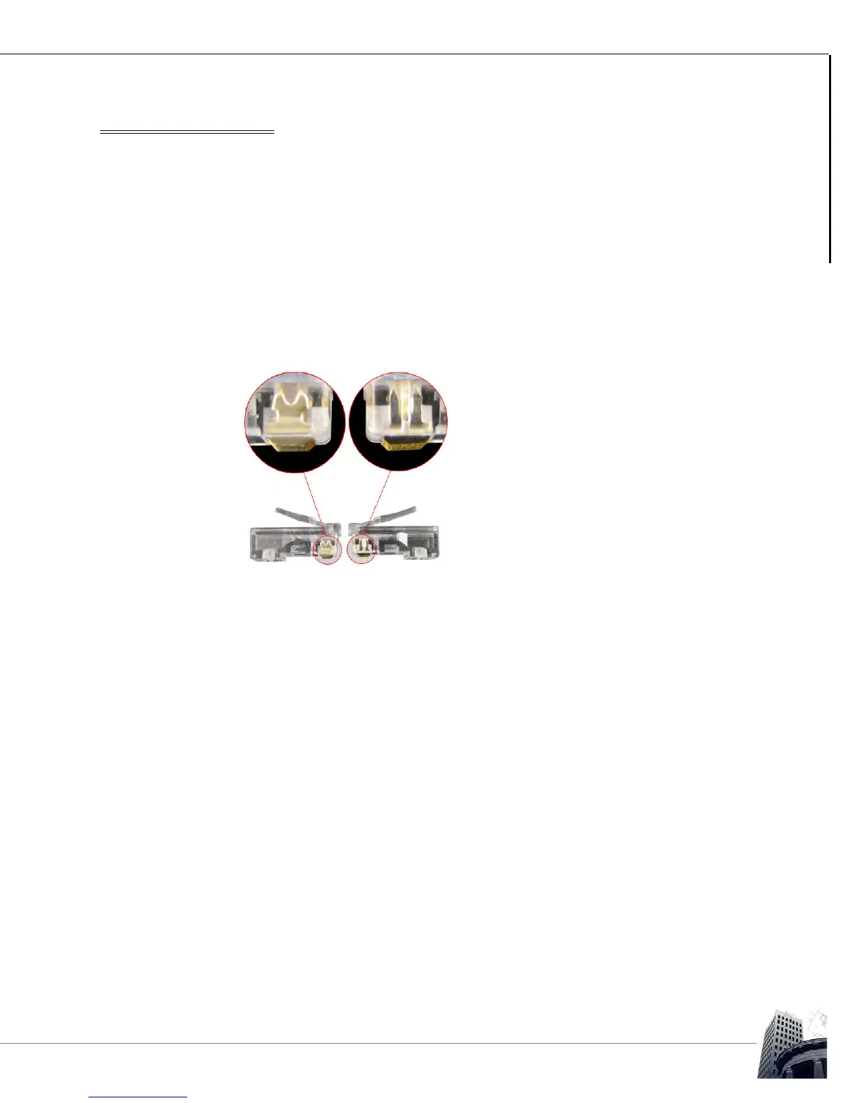
If connection to the RJ11 SMART-Net
™
port at the host controller is required, a
crimped-on RJ11 modular connector will be required. Installers can choose
between using the RJ11 ports or the screw terminals provided at each SMART-
Sensor.
FIGURE 25: RJ11 CONNECTORS FOR SOLID CORE (LEFT) AND STRANDED (RIGHT) CONDUCTORS
3 The recommended RJ11 modular connectors are Tyco 5-555042.3 (for Solid
wire only) and Tyco 5-641337.2 (for Stranded wire only).