Robin 810
Workahop
Manual
Supplement
Fuel system
Section
P
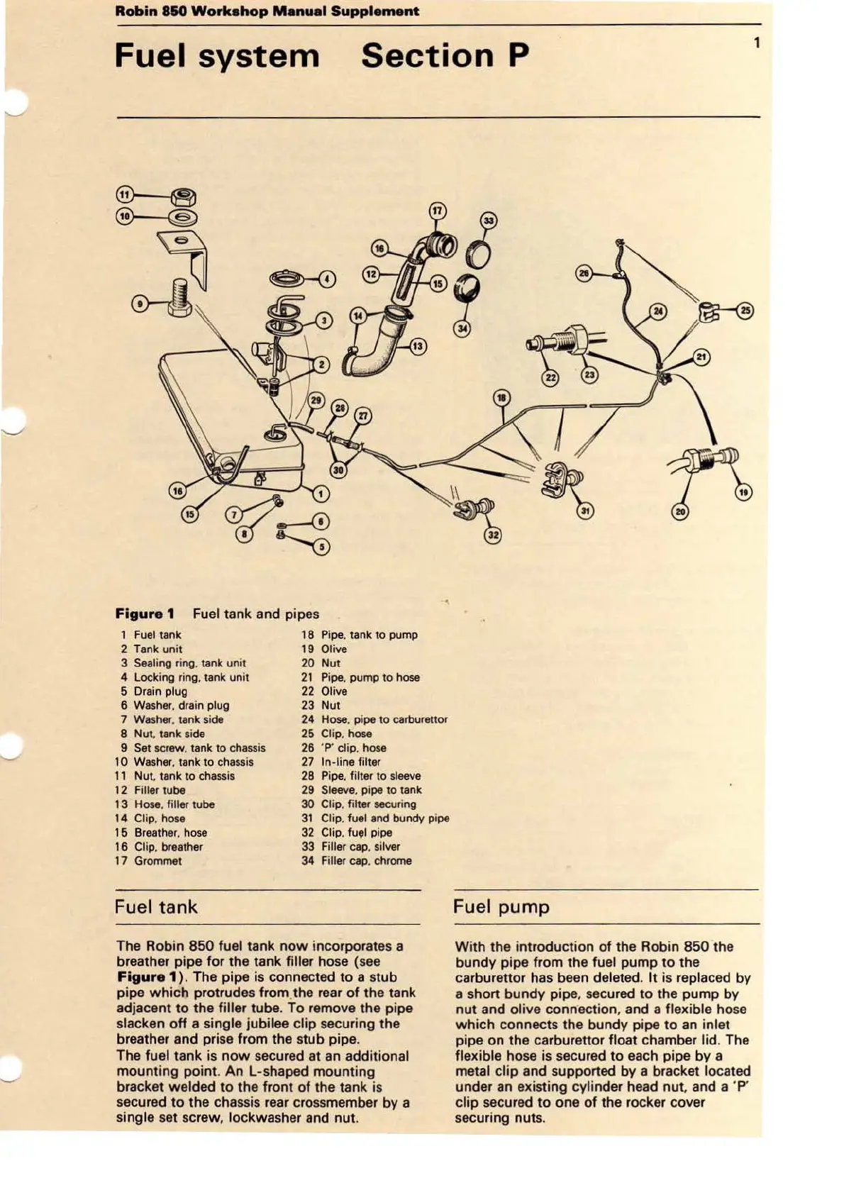
Figure 1
Fu
el tank and pipes
1
Fuel
tank
2 Tank
un
it
3
Sea
li
ng ring, tank un
it
4 Locking
ri
ng. tank unit
5 Drain
plug
6
Washe
r.
drain plug
7 Washer. tank side
8 Nut.
ta
nk side
9 Set screw. tank to ch
assi
s
1
0 Washer. tank
to
chassis
1 1 Nut. tank
to
chassis
12
Filler tube
13
Hose. filler tube
14
Clip.
hose
1 6 Breather.
hose
1 6
Cl
ip, breather
17 Grommet
Fuel
tank
18
Pipe
. tank to pump
19
Oli
ve
20 Nut
21
Pipe, pump
to
hose
22 Oli
ve
23 Nut
24 Hose. pipe to carburettor
25
Clip.
hose
26 '
P'
clip. hose
27
In
-l
ine filter
28 Pipe. filter
to
sleeve
29 Sleeve. pipe to tank
30 Clip. filter securing
31
Clip. fuel
and
bundy pi
pe
32 Clip.
fu<JI
pi
pe
33 Filler cap. silver
34 Fill
er
cap. chrome
The Robin
850
fuel tank
now
incorporates a
breather pipe for the tank
filler hose (see
Figure 1 ). The pipe is connected to a stub
pipe
which
protrudes from_the
rear
of
the tank
adjacent to the
filler tube.
To
remove the pipe
slacken
off
a single jubilee clip securing the
breather and prise from the stub pipe.
The
fuel tank is
now
secured at an additional
mounting point. An L-shaped mounting
bracket
welded
to
the front
of
the tank is
secured
to
the chassis
rear
crossmember by a
single set sc
rew
, lockwasher and
nut
.
Fuel
pump
With the introduction
of
the Robin
850
the
bundy pipe from the
fuel pump to the
carburettor has been
deleted. It
is
replaced by
a short bundy pipe, secured
to
the pump by
nut
and olive connection, and a flexible hose
which
connects the bundy pipe
to
an inlet
pipe on the carburettor float chamber lid. The
flexible hose is secured to each pipe by a
metal
clip
and supported by a bracket located
under an existing cylinder head nut. and a 'P'
clip secured
to
one
of
the rocker cover
securing nuts.
1