Front suspension Section B
7 Mark the position by centre punching the
nut
and stub axle (see
Figure
3).
8 Fit locking ring over retaining nut ensuring
two
of
the castelations line up
with
the split
pin hole in the stub axle shaft. Then
fit
split pin
to
lock hub retaining nut.
9 Move the hub assembly to ensure end
float
is still apparent.
1
0 Refit hub cap.
11
Replace brake drum, retaining
with
single
:\
UNF countersunk screw and readjust front
brake.
12
Refit front wheel, remove stands and jack
down
the vehicle.
Stub axle assembly
To
remove
and
dismantle
(see
Figure
1)
1 Jack up the fro
nt
of
the vehicle and
fit
suitable stands.
2 Remove front hub assembly
as
described in
previous operation.
3 Disconnect brake
fluid flexible hose at the
mounting bracket
bolted
to
the steering arm.
Plug the hose to prevent loss
of
fluid and ingress
of
dirt.
4 Unscrew
i UNF nut, complete
with
plain
washer and disconnect track rod from steering
arm.
5 Unscrew the short and
long
-Ptr
UNF bolts,
complete
with
lockwashers, and remove steering
arm from brake back
plate and stub axle, noting
position
of
flexible brake hose mounting bracket.
Figure
4 Swivel pin removal
6 Remove
two
set screws and
lo
ckwashers
and then
slide the brake plate assembly back
onto the radius
arm
.
7
Drill a small hole in the
two
welch plugs
which
are located in the
top
and bottom
of
the
swivel pin housing
of
the stub axle. The plugs
can then be prised free.
8 Tap out the taper pin, securing the
swivel
pin in position, using a suitable drift.
9 Using
MCA
tool No. P176
as
shown in
Figure
4 or a suitable drift remove the swivel
pin from the stub axle.
3
10
Separate the stub axle from pivot arm and
remove
top
and bottom thrust washers, including
pegged thrust washer.
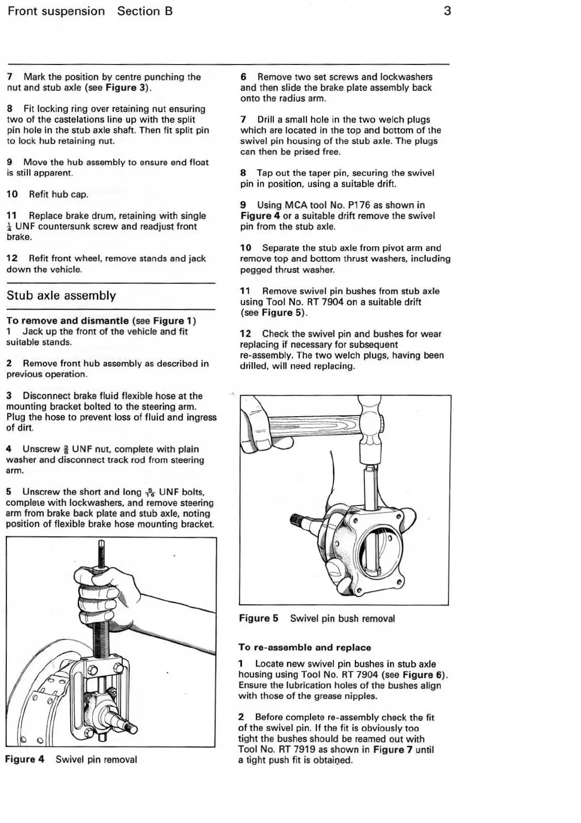
11
Remove swivel pin bushes from stub axle
using Tool No.
RT
7904 on a suitable drift
(see
Figure
5).
12
Check the swivel pin and bushes for wear
replacing
if
necessary for subsequent
re
-assembly. The
two
welch plugs, having be
en
drilled,
will
need replacing.
Figure
5 Swivel pin bush removal
To
re-assemble
and
replace
1 Locate
new
swivel pin bushes in stub axle
housing using Tool No.
RT
7904 (see
Figure
6).
Ensure the lubrication
holes
of
the bushes align
with
those
of
the grease nipples.
2 Before complete
re
-assembly check the
fit
of
the swivel pin.
If
the
fit
is obviously
too
tight
the bushes should
be
reamed
out
with
Tool No.
RT
7919
as
shown in F
igure
7 until
a tight push
fit
is obtaioed.