Front suspension Section B
Description
Front suspension is provided by a Reliant
Motor
Group patented leading
arm
design
controlled by a heavy
duty
combined coil spring
and damper unit.
Chassis mounting is by means
of
two
rubber
bushes and caps locating onto brackets
we
ld
ed
to
the chassis front cross member. A bracket
on the upper cross member provides a mounting
for the damper unit.
Routine maintenance
Other than the greasing
of
the swivel pin and
periodic examination for signs
of
damage and
wear the front suspension assembly requires no
attention except for regular cleaning.
Before dismantling any part
of
the suspension
assembly, jack up the front
of
the vehicle under
the chassis side member and
fit
suitable stands.
Front
hub
and bearings
To
remove
(see
Figure
1)
1 Slacken
off
the front brake adjustment
(see
Section L).
2
Unscrew~
UNF countersunk screw and
remove brake drum.
3 Prise
out
the hub cap and remove split pin
from locking ring and
st
ub axle shaft.
4 Remove locking ring and unscrew front hub
retaining nut.
5 Withdraw front hub assembly complete
with
'0 ' washer, inner and outer taper bearings,
and
oil seal.
6 Remove outer taper bearing and then tap
out
bearing track from hub using a suitable drift.
7 Using the same drift from inside the hub tap
out
the inner bearing track. complete
with
bearing and oil seal.
8 Check components for wear and replace
if
necessary for subsequent reassembly.
To
reassemble
1 Locate inner bearing track in its housing
in
the hub and ensure
it
is firmly and squarely
seated. Then insert taper bearing into bearing
track.
2 Firmly
fit
oil
sea
l and
reta
iner in hub.
3 Repack the front hub
with
the approved
grease in the
area
between the inner bearing
and outer bearing location.
4 Locate outer bearing track in the hub, again
ensuring that
it
is firmly and squarely seated.
Then insert taper bearing into bearing track.
5 Position front hub assembly on the stub
axle and secure with
·o· washer and
fir
UNF
nut
, tightening until all resistance is taken up
when turning the hub.
2
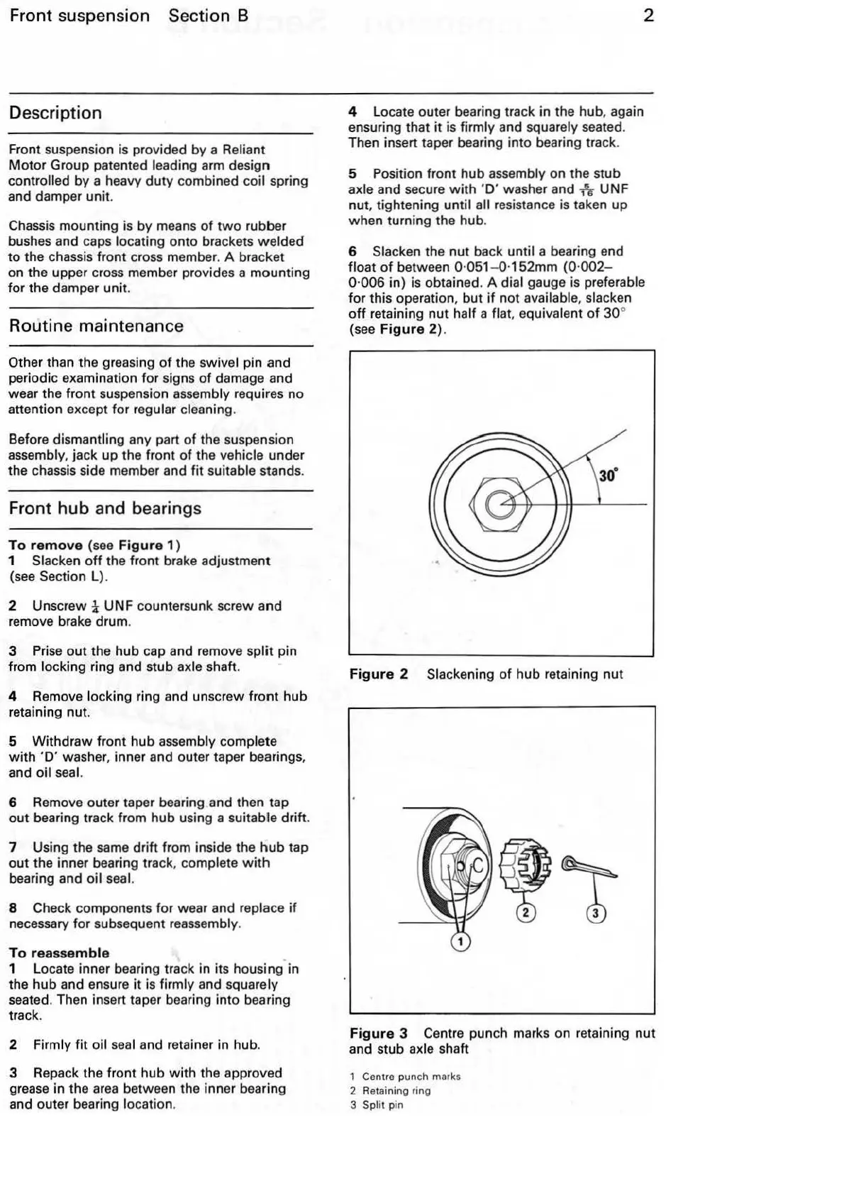
6 Slacken the nut back until a bearing end
float
of
between 0·
051
- 0·152mm
(0
·
002-
0·006 in) is obtained. A dial gauge is preferable
for this operation, but
if
not
available. slacken
off
retaining
nut
half a flat. equivalent
of
30
°
(see
Figure
2).
Figure
2 Slackening
of
hub retaining
nut
Figure
3 Centre punch marks on retaining
nut
and stub axle shaft
1 Centre punch marks
2 Retaining ring
3
Split pin