Electri
cs
Section T
Introduc
tion
From engine number 7942 the 750cc engine
has
incorporated a different distributor to that
describ
ed
on pages 2 to
4.
The service recommendations for this new
di
stributor
are
as
follows:
Lu
brication
of
distributor
The cam and contact breaker plate pivots and
bushing, when
assembling after overhaul, should
be
lubr
icated
with
Shell Retinax
'A'
or
an
equivalent grease. The cam spindle governer
weights and breaker arm pivot
should be
l
ub
ri
cated
with
engine oil every 3,000 miles
(5,000
km). To lubricate the cam spindle
remove the rotor and apply
two
drops
of
oil to
the
felt pad in the top
of
the cam. The felt pad
fitted to the contact breaker, augments
lub
rication
of
the cam. This does
not
require
periodic
lubrication,
as
it
is impregnated before
fitting.
Only a film
of
engine oil should be
applied
to
the
hollow
breaker arm
pivot
post,
ensuring
tha\ none contaminates the distributor
points.
Caution
: Do not over lubricate any part
of
the
distributor. The presence
of
dirt, oil or water on
the ignition points, the
cen
tr
al
carbon brush,
or
in the contact segments in the distributor
cover,
will
cause erratic running
or
may even
p
re
vent the engine from running
at
all.
Contact breaker points
To
adjust
1 Remove the distri
butor
cap and r
otor
arm.
2 Turn the engine so that the
heel
of
the
contact
br
eaker is on the highest
point
of
the
cam.
(It may
be
necessary
to
remove sparking
plugs
to
eliminate the resistance cau!ied by
compression.)
3
Slacken the slotted headed
sc
r
ew
(F
igure
4b)
in the contact plate
an
d adjust until the gap
is 0.38mm (0.015in). The gap is measured
with
a suitable feeler gauge
an
d pressure should be
applied to the points,
with
the feeler gauge
inserted between them,
whilst
the scr
ew
is
being tightened.
4 Retight
en
the screw and make a further
check
with
the feeler gauge in case tightening
the screw has
altered the setting
s.
5 Reposition the rotor arm square
ly
on the
distributor cam boss
with
the sl
ot
and lug in
lin
e.
Pr
ess
the rotor into position on the spindle.
Note
: When the rotor is fitted
to
the spindle the
lower
face
do
es
not abut the cam.
4a
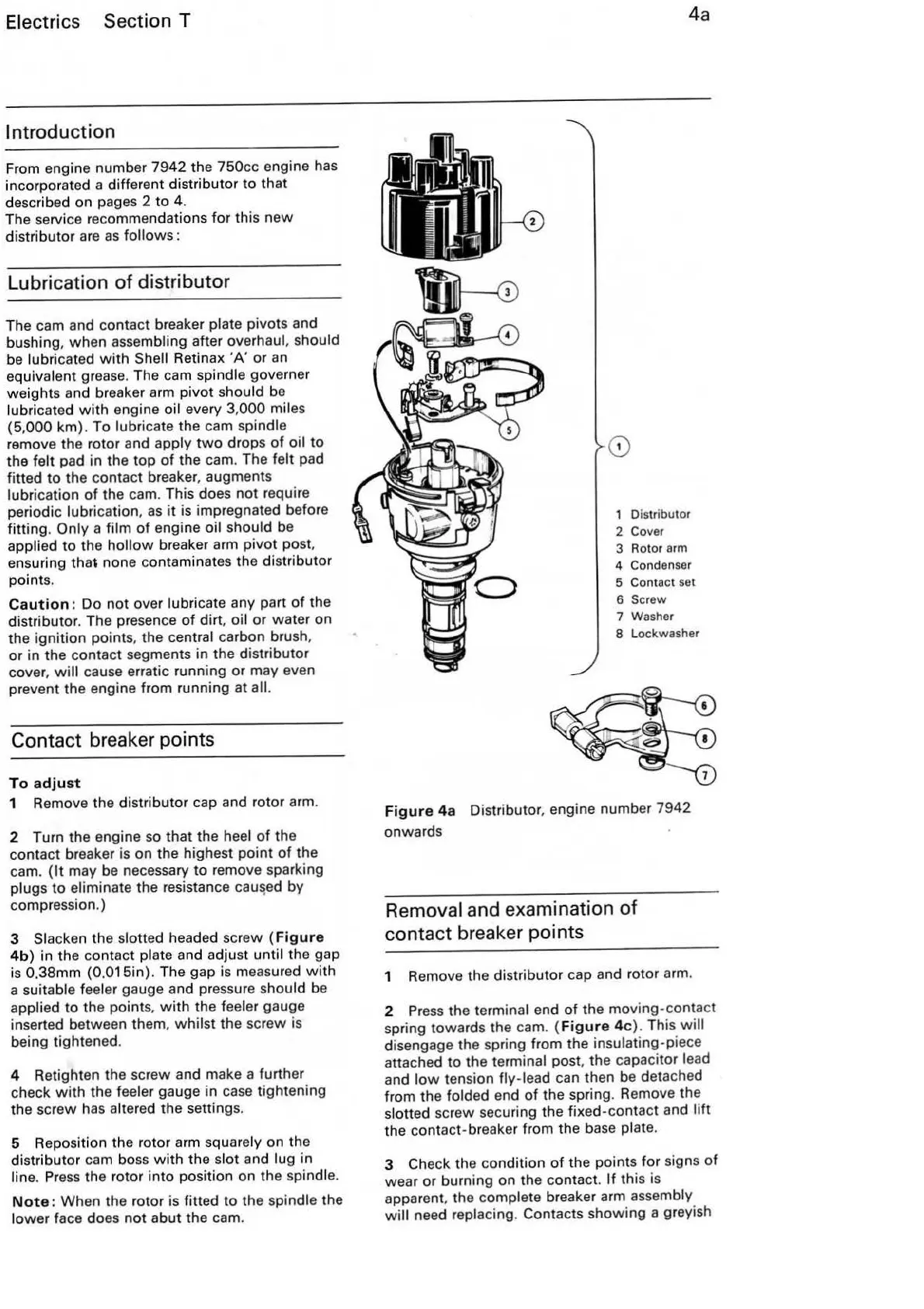
1 Distributor
2 Cover
3 Rotor
arm
4 Condenser
5 Contact set
6 Screw
7 Washer
8 Lockwasher
Figure
4a
Distr
ibuto
r, engine number 7942
onwards
Removal and examination
of
co
nt
act breaker points
1 Remove the distributor cap and rotor arm.
2
Press
the terminal end
of
the moving-contact
spring towards the cam. (F
igu
re 4c). This
will
disengage the spring from the insulating-piece
attached to the
terminal post, the capacitor lead
and
low
tension fly-lead can then be detached
from the
folded
en
d
of
the spring. Remove the
slotted screw securing the fixed-contact and
lift
the contact-breaker from the base plate.
3 Check the condition
of
the points for signs
of
wear
or
burning on the contact.
If
this is
apparent, the
complete breaker arm assembly
wi
ll
need replacing. Contacts showing a greyish