El
ectrics Sec
ti
on T
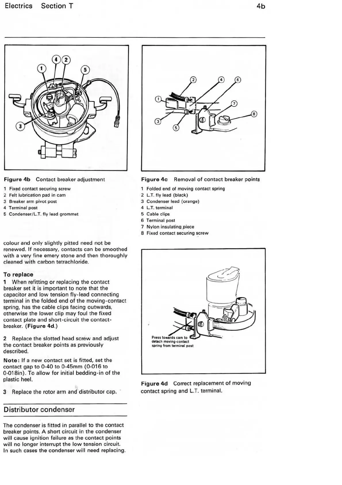
Fi
gu
re
4b
Contact breaker adjustment
Fixed contact securing screw
2
F
el
t lubrication pad in
cam
3 Breaker arm pivot post
4
Terminal post
5 Condenser/ L.T.
fly lead grommet
colour and
only
slightly pi
tt
ed need
not
be
renewed.
If
necessary, contacts can
be
smoothed
with
a very fine emery stone and then thoroughly
cleaned
with
carbon tetrachloride.
To
rep
l
ace
1 When refitting or replacing the contact
breaker set
it
is important to note that the
capacitor and
low
tension
fly
-lead connecting
terminal in the folded end
of
the moving-contact
spring,
has
the cable clips facing outwards,
otherwise the lower
clip may foul the fixed
contact
plate and short-circuit the contact-
breaker. (
Figur
e 4d.)
2 Replace the slotted head screw and adjust
the contact breaker points
as
previously
described.
Not
e:
If
a
new
contact set is fitted, set the
contact gap
to
0·40
to 0·
45mm
(0·016
to
0·018in). To a
ll
ow
fo
r initi
al
bedd
ing-in
of
the
plastic
heel.
3
Rep
lace the rotor arm and distributor cap.
Distribut
or
conden
se
r
The condenser is fi
tt
ed
in parallel to the contact
breaker points. A short circuit in the condenser
wi
ll cause ignition failure
as
the contact points
will
no
longer interr
upt
the l
ow
tension circuit.
In such cases the condenser
will
need replacing.
4b
F
igure
4c Removal
of
contact breaker points
1 Folded end of moving contact spring
2
LT.
fly
lead {black)
3 Condenser lead {orange)
4
LT.
terminal
5 Cable clips
6
Term
inal post
7
Nylon insulating piece
8 Fixed contact securing screw
Figur
e
4d
Correct replacement
of
moving
contact spring and L.T.
terminal.