El
ect
ri
cs Section T
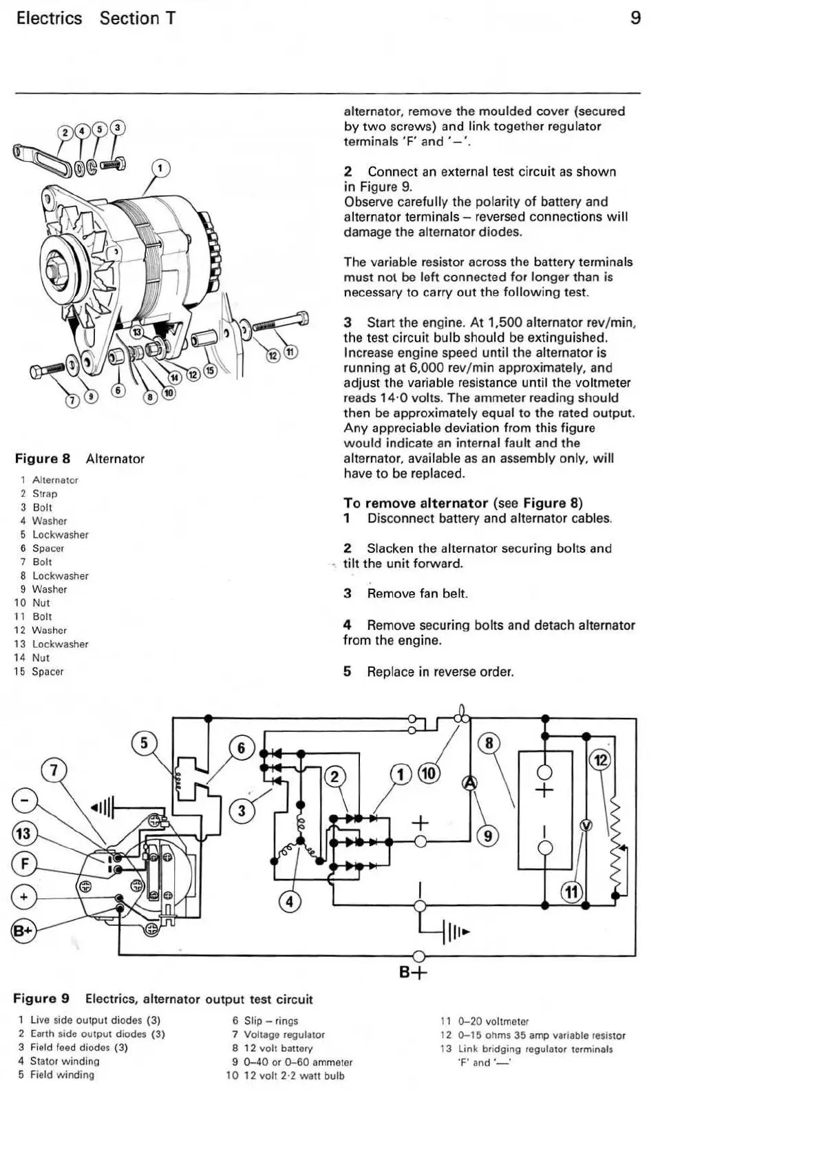
Fig
ur
e 8 Alternator
1 Alternator
2
Strap
3 Bolt
4 Washer
5 Lockwasher
6
Sp
acer
7 Bolt
8 Lockwasher
9 Washer
10
Nut
11 B
olt
12
Washer
13 Lockwasher
14
Nut
15
Sp
acer
alternator, remove the moulded cover (secured
by
two
screws) and
link
together regulator
terminals
'F' and
'-
'.
2 Connect
an
external test circuit
as
shown
in
Figure 9.
Observe
carefully the polarity
of
ba
ttery and
alternator
terminals - reversed connections w ill
damage the alternator diodes.
9
The variable resistor across the battery terminals
must not be left connected for longer than is
necessary to carry
out
the
following
test.
3
Start the engine.
At
1,500 alternator
re
v/
min,
the test circuit
bulb should be extinguished.
Incre
ase
engine speed until the alternator is
ru
nning at 6,000 rev/ min approximately, and
adjust the
variable resistance until the voltmeter
reads
14
·0 volts. The ammeter reading should
then be approximately equal to the rated output.
Any
appreciable deviation from this figure
would
indi
cate an
int
ernal fault and the
alternator, available
as
an assembly onl
y,
will
have
to
be replaced.
To r
emove
a
lt
ernator
(see F
igure
8)
1 Disconne
ct
battery and alternator cables.
2
Slacken the alternator
se
curing bolts and
tilt
the
unit
forward.
3 Remove fan belt.
4 Remove securing bolts and detach alternator
from the engine.
5 Replace in reverse order.
+
B+
Fi
gur
e 9 Electrics, alternator
output
test circuit
1 Live side output diod
es
(3)
2 Earth side output diodes
(3)
3 Field f
ee
d diodes
(3)
4 Stator winding
5
Field winding
6 Slip - rings
7 Voltage regulator
8
12
volt banery
9
0-40
or
0-60
ammeter
10
12
volt 2·2
watt
bulb
11
0-20
voltmeter
12
0-15
ohms 35 amp variable
res
is
tor
13
Link bridging regulator terminals
T
and·-·