El
ectrics Section T
2 Replace inner rim and secure
with
the
three screws.
3
Check the beam setting (see later text) and
then
fit
the front ri
m.
Headlamps (super vehicles)
The Super Rob
in
vehicles have Quartz Halogen
units fitted
as
standard equipment. The
light
unit
is removed
in
the same
way
as
the standard
unit
.
The
light units may be
of
the 'sealed beam' type
or
of
the 'separate bulb' type (see
Figur
e
11
).
The sealed beam
unit
is identical to the standard
sealed beam
unit
and the previous information
applies. The bulb type, however. although
secured
in
a sim
il
ar manner is a metal/glass
reflector and has a separate quartz halogen
bulb,
located in the reflector
with
a spring clip. The
pilot lamp is a separate bulb and is mounted
in
the reflector
with
a push-in bulb holder.
When replacing the quartz halogen bulb the
glass envelope
MUST
NOT be handled
with
the
fin
gers, always hold the bulb
by
the base.
If the envelope is handled it must be cleaned
with
methylated spirit
or
the efficiency
of
the
unit
wi
ll be seriously affected.
Headlamp beam adjus
tm
ent
It is
re
commended that a
Lu
cas 'Beamsetter'
is used
to
ensure accurate beam adjustment.
Follow
the manufacturer's instructions for the
correct procedure.
If
such equipment is
not
available beam adjustment can be obtained by
the
following method:
1 The vehicle should be at its kerbside
we
ight,
with
a person in the driving position,
with
the fuel tank approximately half full and
the tyres at the
cor
rect pressure.
2 Position the vehicle on
level ground
1Om
(32·
8ft)
from, and square to, a
su
itably
darkened screen.
13
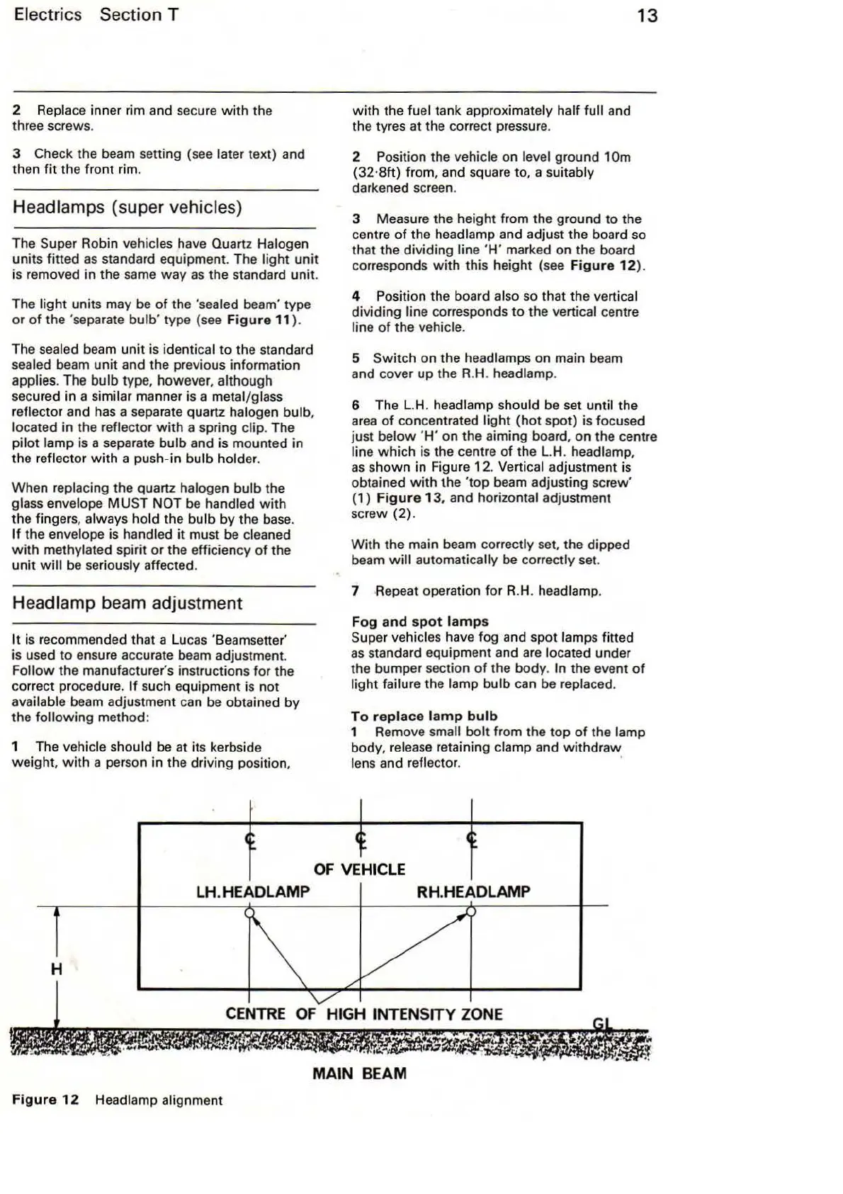
3 Measure the height from the ground to the
centre
of
the headlamp and adjust the board so
that the
divid
ing
lin
e
'H'
marked on the board
corresponds w ith this height (see
Figur
e
12
).
4 Position the board
also so that the vertical
dividing
line co
rr
esponds
to
the vertical centre
line
of
the vehicle.
5
Switch
on
the headlamps
on
main beam
and cover
up
the R.H. headlamp.
6 The L.H. headlamp should be set
until the
area
of
concentrated
light
(hot
spot) is focused
just
below
'
H'
on the aiming board,
on
the centre
line
which
is the centre
of
the L.H. headlamp,
as
shown
in Figure 1
2.
Vertical adjustment is
obtained
with
the
'top
beam adjusting screw'
(1)
Figure
13
, and horizontal adjustment
scr
ew
(2).
With
the main beam correctly set, the dipped
beam
will
automatica
ll
y be correctly set.
7 Repeat operation
for
R.H. headlamp.
Fog
and
spot
lamp
s
S
up
er vehicles have fog and spot lamps fitted
as
standard equipment and
are
located under
the bumper section
of
the
body
. In the event
of
light
failure the lamp
bulb
can
be
replaced.
To
replace
l
am
p
bulb
1 Remove small
bolt
from the top
of
the lamp
body, release retaining clamp and
withdraw
lens and reflector. ·
OF
VEHICLE
LH.HEADLAMP RH.HEADLAMP
H
CENTRE
OF
HIGH INTENSITY
ZONE
MAIN BEAM
Figure
12
Headlamp alignment