El
ectrics Section T
F
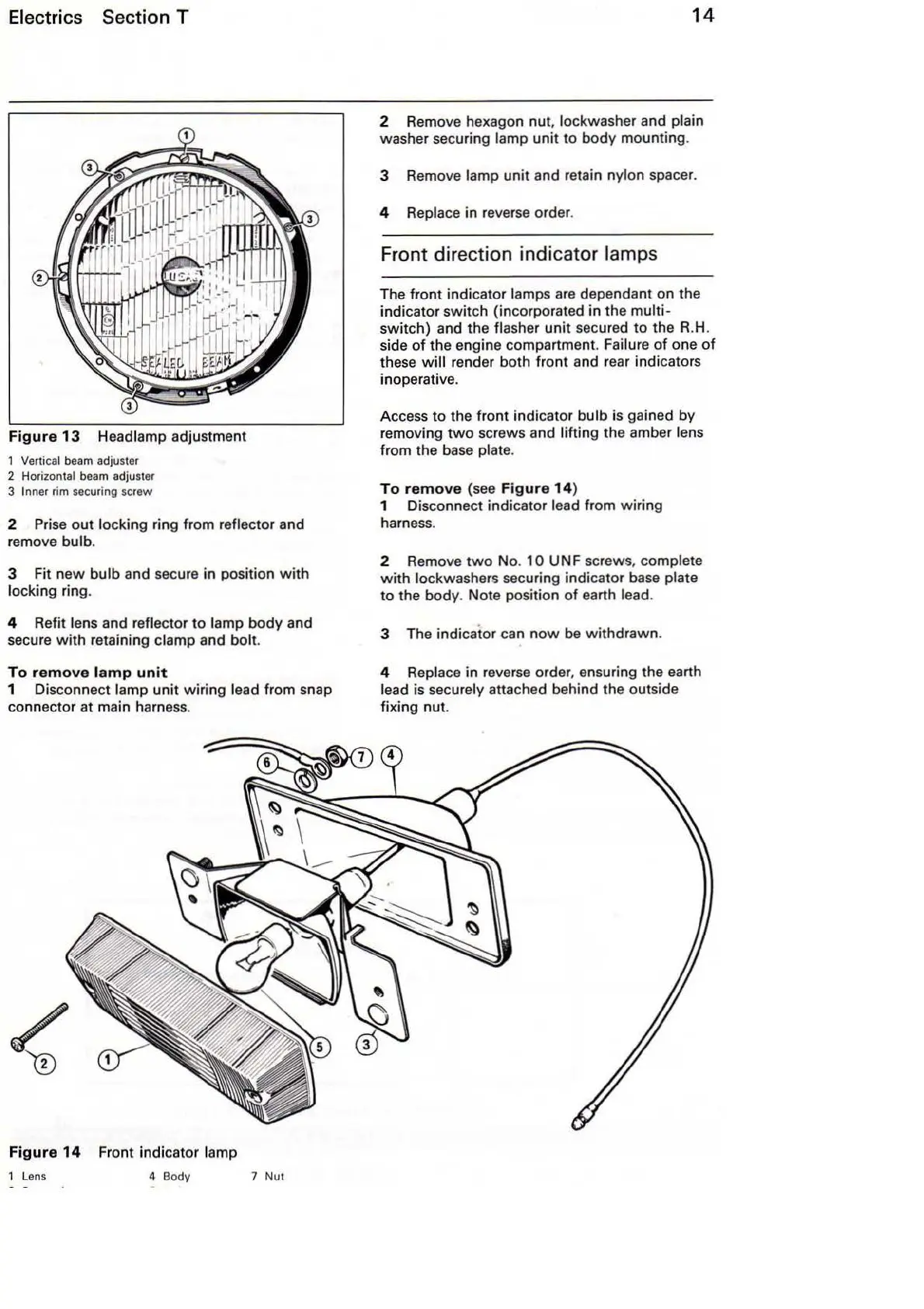
igure
13 Headlamp adjustment
1
Ve
rtical beam adjuster
2 Horiz
ont
al be
am
ad
juster
3 Inner rim securing screw
2 Prise
out
locking ring from reflector and
remove
bulb.
3 Fit
new
bulb
and secure in position
with
locking ring.
4 Refit lens and reflector
to
lamp body and
secure
with
retaining clamp and bolt.
To
remove
l
amp
un
it
1 Disconnect lamp unit wiring lead from snap
connector at main harness.
Fi
g
ur
e
14
Front indicator lamp
1
Len
s 4 Body 7 Nut
14
2 Remove hexagon
nut
, lockwasher and plain
washer securing lamp unit to body mounting.
3 Remove
lamp unit and retain nylon spacer.
4 Replace
in
reverse order.
Fr
ont
direction indicator lamps
The front indicator lamps are dependant
on
the
indicator switch (incorporated in the
multi-
switch) and the flasher unit secured
to
the R.
H.
side
of
the engine compartment. Failure
of
one
of
these
will
render both front and rear indicators
inoperative.
Access
to
the front indicator
bulb
is gained by
removing
two
screws and lifting the amber lens
from the
base
plate.
To
re
m
ove
(see F
igure
14)
1 Disconnect indicator lead from wiring
harness.
2 Remove
two
No. 1 0 UN F screws, complete
with
lockwashers securing indicator
base
plate
to the body. Note position
of
earth lead.
3 The indicator can
now
be withdrawn.
4 Replace in reverse order, ensuring the earth
lead is securely attached behind the outside
fixing nut.