Electrics Section T
instrument indicates the battery operating
voltage.
Oil
pressure
gauge
-
Super
models
only
Located to the right above the centre console
this meter indicates that oil is circulating the
engine under the correct pressure. When
starting from
cold the gauge may
show
a high
initial pressure,
but
will
gradually fall
to
about
3·16kg/sq
em
(451b/ sq
in)
for
normal engine
speeds
as
the engine temperature rises.
If
a very
low
indication is given,
or
the instrument shows
no
pressure
at
all, the engine should be switched
off
immediately and the oil level checked by
means
of
the engine dipstick.
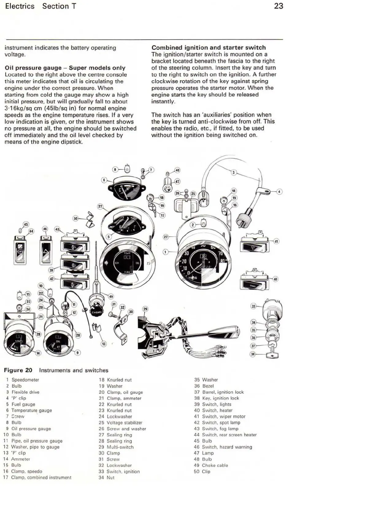
F
igure
20
Instruments and
sw
itches
1
Speedometer 18 Knurled
nut
2 Bulb 19 Washer
3 Flexible drive
20 Clamp. oil gauge
4
·p· clip
21
Clamp. ammeter
5
Fuel
gauge
22
Knurled
nut
6 Temperature gauge
23
Knurled
nut
7 S-:rew 24 lockwasher
8 Bulb 25 Voltage stabilizer
9
Oil pressure gauge
26
Screw and washer
10
Bulb
27
Sea
ling ring
11
Pipe. oil pressure gauge 28 Sealing ring
12
W
as
her. pipe to gauge
29
Multi-switch
13 'P
'c
llp
30 Clamp
14 Ammeter
31
Screw
15 Bulb
32
lockwasher
16
Clamp. speedo
33 Switch. ignition
17
Clamp. combined Instrument
34
Nut
23
Combined
ignition
and
starter
switch
The ignition/starter
swit
ch is mounted on a
bracket
located beneath the fascia
to
the right
of
the steering column. Insert the key and turn
to the r
ight
to
switch
on
the ignition. A further
clockwise rotation
of
the key against spring
pressure operates the starter motor. When the
engine starts the key
should
be
released
instantly.
The
switch
has an 'aux
il
iaries' position when
the key is turned
anti-clockwise from off. This
enables the radio, etc
.,
if fitted,
to
be used
without
the ignition being switched on.
35 Washer
36
Bezel
37 Barrel. ignttion lock
38
Key.
tgnltion lock
39
Swttch. ltghts
40
Switch. heater
41
Switch. wtper motor
42 Switch. spot lamp
43
Switch. fog lamp
44 Switch. r
ear
screen heater
45 Bulb
46
Swttch. hazard warning
47 Lamp
48 Bulb
49
Choke cable
50 Clip