The engine Section F
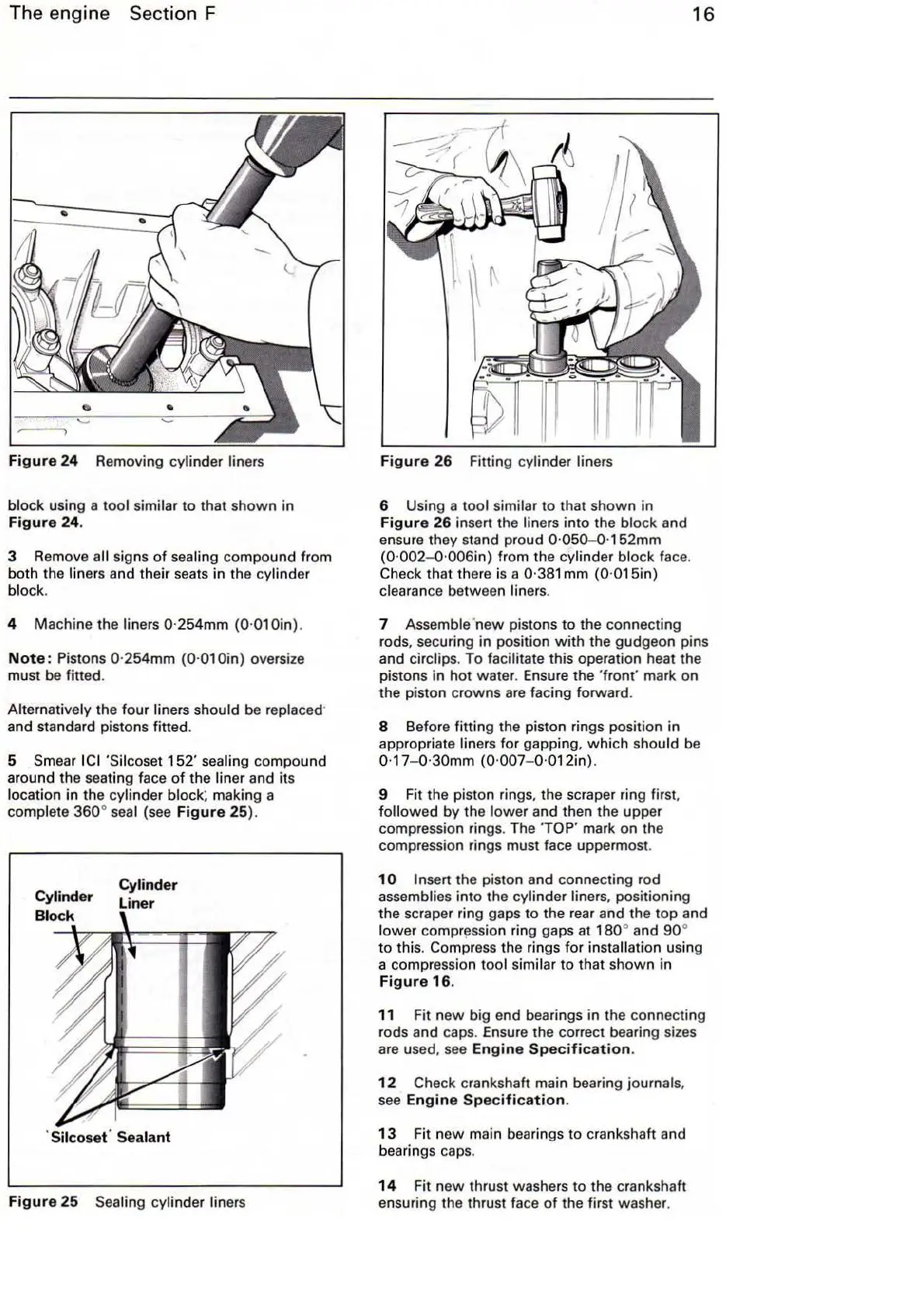
Figure
24
Removing cylinder liners
block
using a tool similar to that shown in
Figure
24
.
3 Remove all signs
of
sealing compound from
both the
liners and their seats
in
the cylinder
block.
4 Machine the liners 0·254mm {0·01 Oin).
Note
: Pistons 0·254mm (0·010in) oversize
must
be
fitted.
Alternatively the four liners should be replaced·
and standard pistons fitted.
5
Smear I
CI
'Silcoset
152
' sealing compound
around the seating face
of
the liner and its
location
in
the cylinder
block
~
making a
complete 360°
sea
l (see
Figure
25
).
Cylinder
Liner
·
Silcosef
Sealant
Figure
25
Sea
ling
cy
lind
er
liners
Figure
26
Fitting cylinder liners
6 Using a tool similar to that shown in
Figure
26 insen the liners into the block and
ensure they stand proud
0·050-0·152mm
{0·002- 0·006in) from the cylinder block face.
Check that there is a 0·381
mm
{0·015in)
clearance
between liners.
16
7 Assemble'
new
pistons to the connecting
rods, securing in position
with
the gudgeon pins
and
circlips. To facilitate this operation heat the
pistons
in
hot
water. Ensure the
'fro
nt'
mark on
the piston crowns are facing forward.
8 Before fitting the piston rings position in
appropriate
liners for gapping,
which
should be
0·17-0
·30mm
(0·007-0
·012in).
9 Fit the piston rings, the scraper ring first,
followed
by the
lower
and then the upper
compression rings. The
TOP'
mark on the
compression rings must face uppermost.
1
0 I nsen the piston and connecting rod
assemblies
into
the cylinder liners, positioning
the scraper ring gaps
to
the rear and the top and
lower
compr~ssion
ring gaps at
180
° and
90
°
to this. Compress the rings for installation using
a compression
tool similar to that shown in
Figure
16
.
11
Fit
new
big end bearings in the connecting
rods and caps. Ensure the correct bearing sizes
are used, see
Engine
Specification
.
12
Check crankshaft main bearing journals,
see
Engine
Specification.
13
Fit new main bearings to crankshaft and
bearings caps.
14
Fit
new
thrust washers
to
the crankshaft
ensuring the thrust
fa
ce
of
the first washer.