4
24
Re
connect water pump and thermostat
housing hoses
to
manifold adaptor.
26
Reconnect choke cable and accelerator
cable
at carburett
or
.
26
R
efit
air cleaner.
27
Reconnect high and
low
tension leads
at coil.
28
Reconnect oil pressure warning light l
ead
.
or
oil pressure pipe
if
gauge is fitted.
29
Reconnect temperature gauge sender unit
lead at thermostat housing.
30
Reconnect starter motor lead.
31
Refit alternator and connect leads.
32
Reconnect heater hose at cylinder head
adaptor. refit
jubilee clip and secure hose
to
mounting bracket attached
to
rocker cover
stud.
33 Reconnect heater hose at water pump
and secure
with
jubil
ee
clip.
34
Reconnect radiator bottom hose at
water pump.
35
Reconnect radiator top hose at thermostat
housing.
36
Refill engine and gearbox
with
recommended oil.
37 Refill the cooling system.
38
R
econnectbatte~
.
Operation 2 - Flywheel and ring
gear
removal and replacement
Flywheel
removal
1 Remove the gearbox (see
Section
G).
2 Unscrew six set screws.
complete
with
lockwashers. and remove the clutch assembly
from the flywheel.
3 Release the tabwasher. unscrew three set
screws, and remove the
flywheel assembly
from the crankshaft.
Starter
ring
gear
removal
1 Drill a hole
6·35mm
(0
·
25i
n) diameter at
the point
of
intersection
of
a scribed line
between any
two
teeth and a scribed line
midway between the r
oot
diameter and the
inside diameter
of
th
e ring gear.
En
sure that
the
hole is
not
drilled through the ring gear
into the
flywheel.
as
this
will
interfere
with
the
subsequent
balance
of
the flywheel.
The engine
2 Hold
th
e flywheel assembly in a soft-jawed
vice.
3
Place a
clot
h
of
heavy material over the
ring gear
as
a protection against flying
fragments.
Warning
:
En
sure adequate protection,
particularly for the eyes,
to
prevent injury from
the
possibility
of
flying fragments when the
ring gear is
split.
4 Place a cold chisel immediately above the
centre
line
of
the drilled hole and strike
sharply
to
split the ring gear.
Refitting
1 Heat the replacement ring gear uniformly
to
a maximum
of
200"C.
2 Place the flywheel on a flat surface. clutch
face side uppermost. and clean the ring gear
locating surface.
3 Locate the ring gear and
hold in position
until
it
contracts sufficiently
to
grip the
flywheel.
4
Allow
the ring gear
to
cool gradually
to
avoid distortion.
'
C>
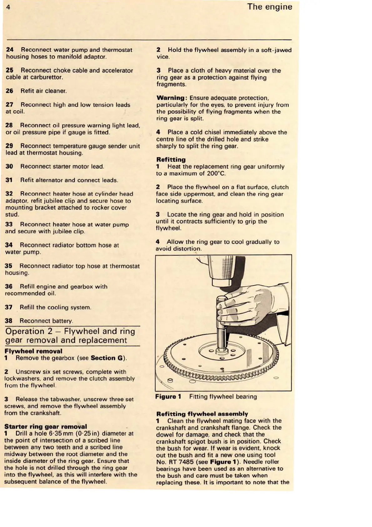
Figure
1 Fitting flywheel bearing
Refitting
flywheel
assembly
1 Clean the flywheel mating face
with
the
crankshaft and crankshaft
flange. Check the
dowel for damage, and check that the
crankshaft spigot bush is in position.
Check
the bush for wear.
If
wear is evident, knock
out
the bush and
fit
a
new
one using tool
No.
RT
7485
(see
Figure
1)
. Needle roll
er
bearings have been used
as
an
alternative
to
the bush and care must be taken when
replacing these.
It
is important
to
note that the