Robin
850
Workshop
Manual
Supplement
The engine
hardened, square end face
of
the bearing must
face the
tool
used
to
press in the bearing. Use
of
the rolled end
of
the bearing
will
lead to
shell distortion and needle failure. The
manufacturer's name and designation number
may be stamped on the hardened end face in
so
me
instances, enabling
it
to be easily
identified. However, this does
not
apply
with
all manufacturers and care should be
exercised
to
identify the correct end by its
shape.
2 Fit the flywheel
to
the crankshaft, locating
over the dowel in the crankshaft.
3 Secure the flywheel assembly to the
crankshaft
with
three set screws. and a
tabwasher, tightening
to
a torque
of
4·
03
kg m
(291bft). The tabs
of
the
washer should then
be bent over to lock the set screws.
4 Check the flywheel for misalignment using
a clock indicator gauge. A
0·
08-0
·
13
mm
(0
·
003
-
0·005
in) run-out is permitted, but
if
this is exceeded the flywheel must be
replaced
with
a
new
assembly.
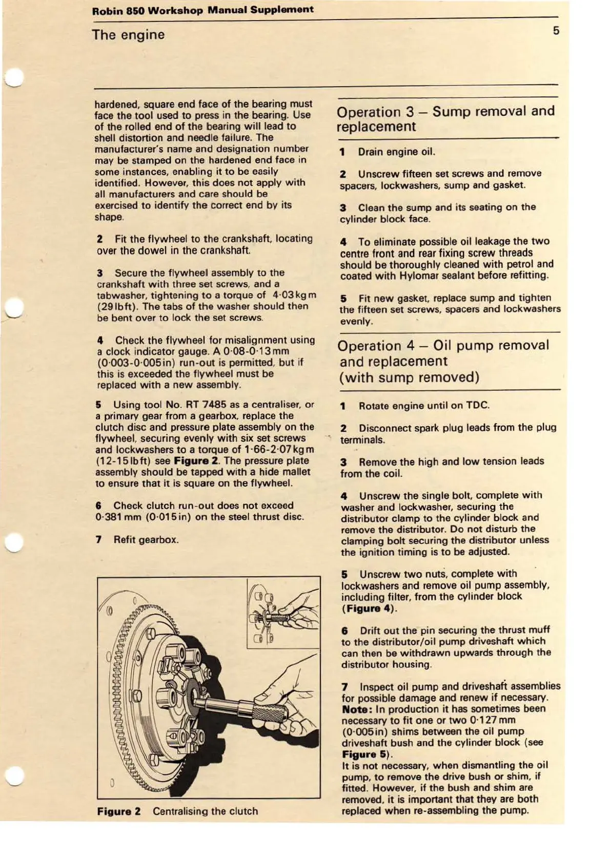
5 Using tool
No
.
RT
7485
as
a centraliser, or
a primary gear from a gearbox, replace the
clutch disc and pressure plate assembly on the
flywheel, securing evenly
with
six set screws
and lock washers to a torque
of
1·66-2
·
07
kg m
(12-151bft)
see
Figure
2.
Th
e pressure plate
assembly should be tapped
with
a hide mallet
to
ensure that
it
is square on the flywheel.
6 Check clutch run
-o
ut
does
not
exceed
0·381 mm
(0
·
015
in)
on
the steel thrust disc.
7 Refit gearbox.
Figure
2 Centralising the clutch
5
Operation 3 -
Sump
removal and
replacement
1 Drain engine oil.
2 Unscrew fifteen set screws and remove
spacers, lockwashers, sump and gasket.
3 Clean the sump and its seating on the
cylinder block face.
4
To
eliminate possible oil leakage the
two
centre front and
rear
fixing screw threads
should be thoroughly cleaned
with
petrol and
coated
with
Hylomar sealant before refitting.
5 Fit
new
gasket, replace sump and tighten
the fifteen set
sc
rew
s, spacers and lockwashers
evenly.
Operation 4 - Oil
pump
removal
and replacement
(with
sump removed)
1 Rotate engine until on TDC.
2 Disconnect spark plug leads from the plug
terminals.
3 Remove the high and
low
tension leads
from the
coil.
4 Unscrew the single
bolt
, complete
with
washer and lockwasher, securing the
distributor clamp to the cylinder block and
remove the distributor. Do not disturb the
clamping
bolt
securing the distributor unless
the
ignition timing is
to
be adjusted.
5 Unscrew
two
nuts, complete
with
lockwashe
rs
and remove oil pump assembly,
including
filter, from the cylinder block
(Figure
4).
6 Drift out the pin securing the thrust muff
to the distributor/oil pump driveshaft
which
can then be
withdrawn
upwards through the
distributor housing.
7 Inspect oil pump and driveshatt assemblies
for possible damage and renew
if
necessary.
Note:
In production
it
ha
s sometimes been
necessary
to
fit
one
or
two
0·127 mm
(0
·
005
in) shims between the oil pump
driveshaft bush and the cylinder block (see
Figure&)
.
It
is not necessary, when dismantling the oil
pump,
to
remove
the
drive bush
or
shim,
if
fitted. However,
if
the bush and shim are
removed,
it
is important that they are both
replaced when re-assembling the pump.