Robin
850
Wor
ks
hop
Manu
al
Suppleme
nt
The e
ngin
e
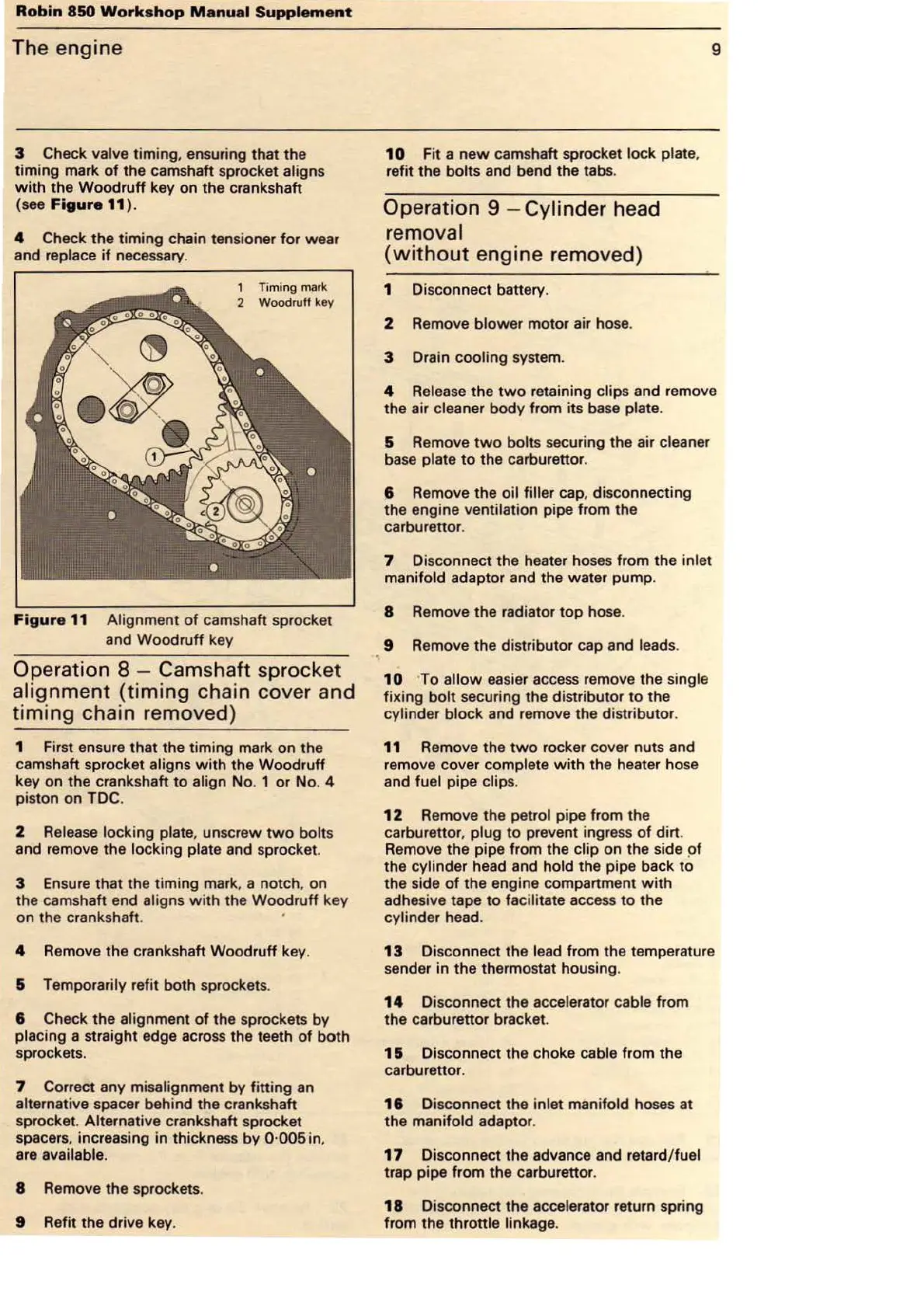
3 Check valve timing, ensuring that the
timing mark
of
the camshaft sprocket aligns
with
the Woodru
ff
key on the crankshaft
(see
Figure
11 ).
4 Check the timi
ng
chain tensioner
for
wear
and
replace
if
necessary.
1 Ti
ming
mark
2
Wood
r
uff
key
Fi
gur
e 11 Alignment
of
cam
sha
ft
sprocket
and Woodruff key
Operation 8 - Camshaft spr
ocket
al
ignment
(tim
ing chain cover and
timing
chain removed)
1 First ensure that the timing mark on the
camshaft s
pr
ocket aligns
with
the Woodruff
key on the crankshaft
to
align
No
. 1 or No. 4
piston on TDC.
2 Release locking plate, unscrew
two
bolts
and remove the locking plate and sprocket.
3
En
sure
that
th
e timing mark, a notch, on
th
e c
am
shaft end aligns
with
th
e Woodruff key
on
th
e cran
ks
ha
ft
. ·
4 Remove the cranksha
ft
Woodruff key.
& Temporarily refit both sprockets.
8 Check the alignment
of
the sprockets by
placing a straight edge across
th
e teeth
of
both
sprockets.
7 Correct any misalignment
by
fitting an
alternative spacer behind the crankshaft
sprocket.
Alternative crankshaft sprocket
spacers, increasing in thickness by
0·005in
,
are available.
8 Remove the sprockets.
9 R
efit
the drive key.
10
F
it
a n
ew
camshaft sprocket lock plate,
refit the bolts and bend the tabs.
Operation 9 - Cylinder h
ea
d
re
moval
(w i
thout
en
gine
re
mo
ved)
1 Disconnect battery.
2 Remove bl
ower
motor air hose.
3 Drain cooling system.
9
4 Release the
two
retaining clips and remove
the air
cleaner body from its base plate.
5 Remove
two
bolts securi
ng
the air cleaner
base plate
to
the carburettor.
8 Remove the
oi
l filler cap, disconnecting
the engine
ventila
tion
pipe from the
carbu
re
tto
r.
7 Disconnect the heater hoses from the inlet
manifold
adaptor and the water pump.
8 Remove the radiator top
ho
se.
9 Remove the d
is
tributor cap and leads.
10
To
allow
ea
sier access remove the single
fix
ing bolt securing the distributor
to
the
cylinder block and remove the distributor.
11 Remove the
two
rocker
co
ver nuts and
remove cover
complete
with
the heater
ho
se
and
fuel pipe clips.
1 2 Remove the petrol pipe from the
carbure
ttor
, plug
to
prevent ingress
of
dirt
.
Remove the pipe from the
clip on the side
pf
the cylinder head and
ho
ld the pipe back
to
the side
of
the engine compartment wi
th
adhesive tape
to
facilitate acce
ss
to the
cylinder head.
13
Disconnect the lead from
th
e temperature
sender in the thermostat housing.
14
Disconnect the accelerator cable from
the carburettor bracket.
1 & Dis
co
nn
ect the choke cable from the
carburettor.
18
Disconnect the inlet manifold hoses at
the
manifold adaptor.
17
Disconnect the advance and retard/ fuel
trap pipe from the carburettor.
18
Disco
nn
ect the accelerator return spring
from the
throttle linkage.