Robin
850
Workshop
Manual
Supplement
The engine
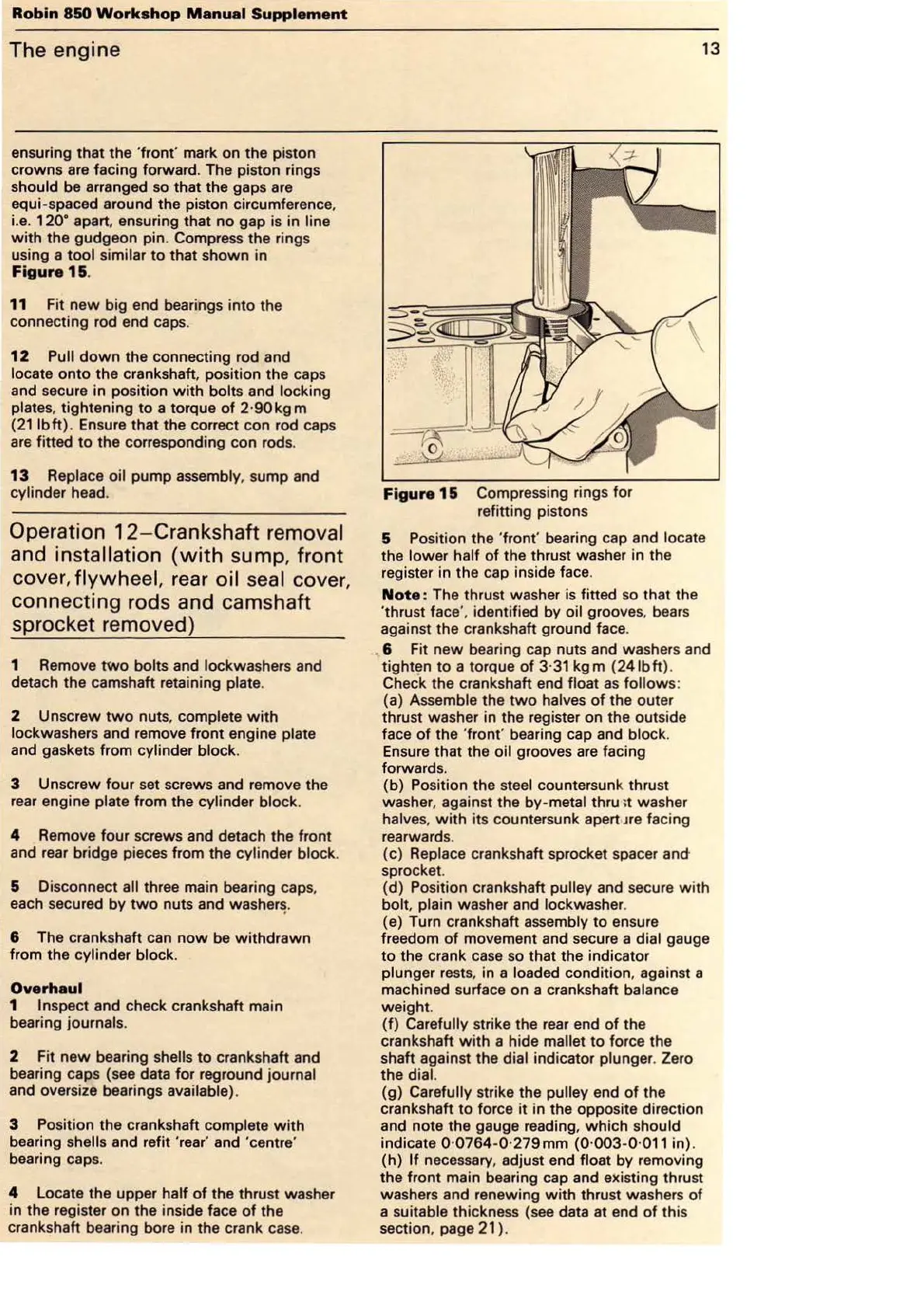
ensuring that the
'f
ront' mark on the piston
crowns are facing forward. The piston rings
should be arranged so that the gaps are
equi-spaced around the piston circumference.
i.e.
120
• apart. ensuring that no gap is in line
with
the gudgeon pin. Compress the rings
using a
tool similar to that shown in
Figure
1&.
11 Fit new big end bearings into the
connecting rod end caps.
12
Pull
down
the connecting rod and
locate onto the crankshaft. position the caps
and secure in position
with
bolts and locking
plates,
tightening
to
a torque
of
2
·90kg
m
(211bft). Ensure that the correct con rod caps
are fitted
to
the corresponding con rod
s.
13
Replace oil pump assembly, sump and
cylinder head.
Operation
12
- Crankshaft removal
and installation
(with
sump
, front
cover,
flywheel, rear
oil
seal cover,
connecting rods and camshaft
sprocket removed)
1 Remove
two
bolts and lockwashers and
detach the camshaft retaining
plate.
2 Unscrew
two
nuts, complete
with
lockwashers and remove front engine plate
and gaskets from cylinder block.
3 Unscrew
four
set screws and remove the
rear engine
plate from the cylinder block.
4 Remove four screws and detach the front
and rear bridge pieces from the
cylinder block.
& Disconnect all three main bearing caps,
each secured by
two
nuts and
washer~
.
6 The crankshaft can
now
be
withdrawn
from the cylinder block.
Overhaul
1 Inspect and check crankshaft main
bearing
journals.
2 Fit new bearing shells
to
crankshaft and
bearing caps (see data for reground
journal
and oversize bearings available).
3 Position the crankshaft complete
with
bearing shells and refit 'rear' and 'centre'
bearing caps.
4 Locate the upper half
of
the thrust washer
in the register on the inside face
of
the
crankshaft bearing bore in the crank case.
13
Figure 1 & Compressing rings for
refitting pistons
5 Position the
'f
ront' bearing cap and locate
the lower half
of
the thrust washer in the
register in the cap inside face.
Note
: The thrust washer
is
fitted
so
that the
'thrust
face
',
identified by oil grooves,
bears
against the crankshaft ground face .
. 6 F
it
new bearing cap nuts and washers and
tighten
to
a torque
of
3·
31
kgm
(241bft).
Check the crankshaft end float
as
follows:
(a) Assemble the
two
halves
of
the outer
thrust washer in the register on the outside
face
of
the
'f
ront' bearing cap and block.
Ensure that the oil grooves
are
facing
forwards.
(b) Position the
steel countersunk thrust
washer, against the
by-metal thru >t washer
halve
s,
with
its countersunk apert
Jre
facing
rearwards.
(c)
Replace crankshaft sprocket spacer
and
sprocket.
(d)
Po
sition crankshaft pulley and secure
with
bolt, plain washer and lockwasher.
(e) Turn crankshaft assembly to ensure
freedom
of
movement and secure a dial gauge
to the crank
case
so that the indicator
plunger rest
s.
in a loaded condition, against a
machined surface on a crankshaft
balance
weight.
(f)
Carefully strike the
rear
end
of
the
crankshaft
with
a hide mallet to force the
shaft against the
dial indicator plunger. Zero
the dial.
(g) Carefully strike the pulley end
of
the
crankshaft
to
force
it
in the oppo
si
te direction
and note the gauge reading,
which
should
indicate 0·
0764
-0·279mm
(0
·
003
-0·
011
in).
(h)
If
necessary, adjust end float by removing
the front main bearing cap and existing thrust
washers and renewing
with
thrust washers
of
a suitable thickness (see data at end
of
this
section, page
21
).