20
24
Replace crankshaft pulley and secure
with
bolt
, plain washer and lockwasher.
21
Locate a
new
gasket and then
fit
the oil
pump assembly, complete
with
filter, securing
to
the cylinder block
with
two
nuts and
lockwashers. Refit
oil pump and distributor
drive shaft.
21
Fit a
new
gasket and replace the sump,
tightening the fifteen set screws, spacing
washers and lockwashers evenly.
27
Clean the cylinder head and cylinder
block faces and
fit
a new gasket. Smear grease
around the metal edges
of
the gasket bore
eyelets.
28
Carefully position the cylinder head
squarely on the cylinder block and secure
with
the twelve nuts, plain washers and
lockwashers. Replace the three nuts on the
spark
plug side
of
the cylinder head. Check
that
all cylinder head nuts indicated in
Figure13
are tightened, in the order shown,
to
a torque
of
3·46kgm
(251bft). The three
remaining nuts, on the spark
plug side, should
be tightened
to
a torque
of
2·
07
kg m
(151bft).
29 Replace the push rods ensuring they
are
replaced in their correct order.
30 Locate the rocker shaft assembly on the
four studs and secure firmly
with
the four nuts
and washers
to
a torque
of
2·35-3·
04kgm
(17-221bft). Check tappet clearance (see
Operation
17)
.
31
Fit a
new
gasket and replace the rocker
cover securing in position
with
the
two
nuts
and washers.
32
Replace all ancillaries.
33
Install the engine and gearbox assembly
(see
Operation
1 ) .
Operation 1 7 - Valve clearance
-tappet
adjustment
Tappet clearances are 0·
152
mm
(0
·
006
in)
cold,
0·254 mm
(0
·
01
Oin) hot.
To
adjuat
1 Remove rocker cover, secured
by
two
nuts.
2 Remove spark plugs.
3 Turn engine in normal running direction in
order
to
open and close the valves and check
The engine
in the
following
order:
No
'. 1 valve
with
No
. 8 valve fully open
No
. 2 valve
with
No
. 7 valve fully open
No
. 3 valve
with
No. 6 valve fully open
No
. 4 valve
with
No. 5 valve
fully
open
No
. 5 valve
with
No
. 4 valve fully open
No
. 6 valve
with
No
. 3 valve
fully
open
No
. 7 valve
with
No
. 2 valve fully open
No.
8 valve
with
No
. 1 valve
fully
open
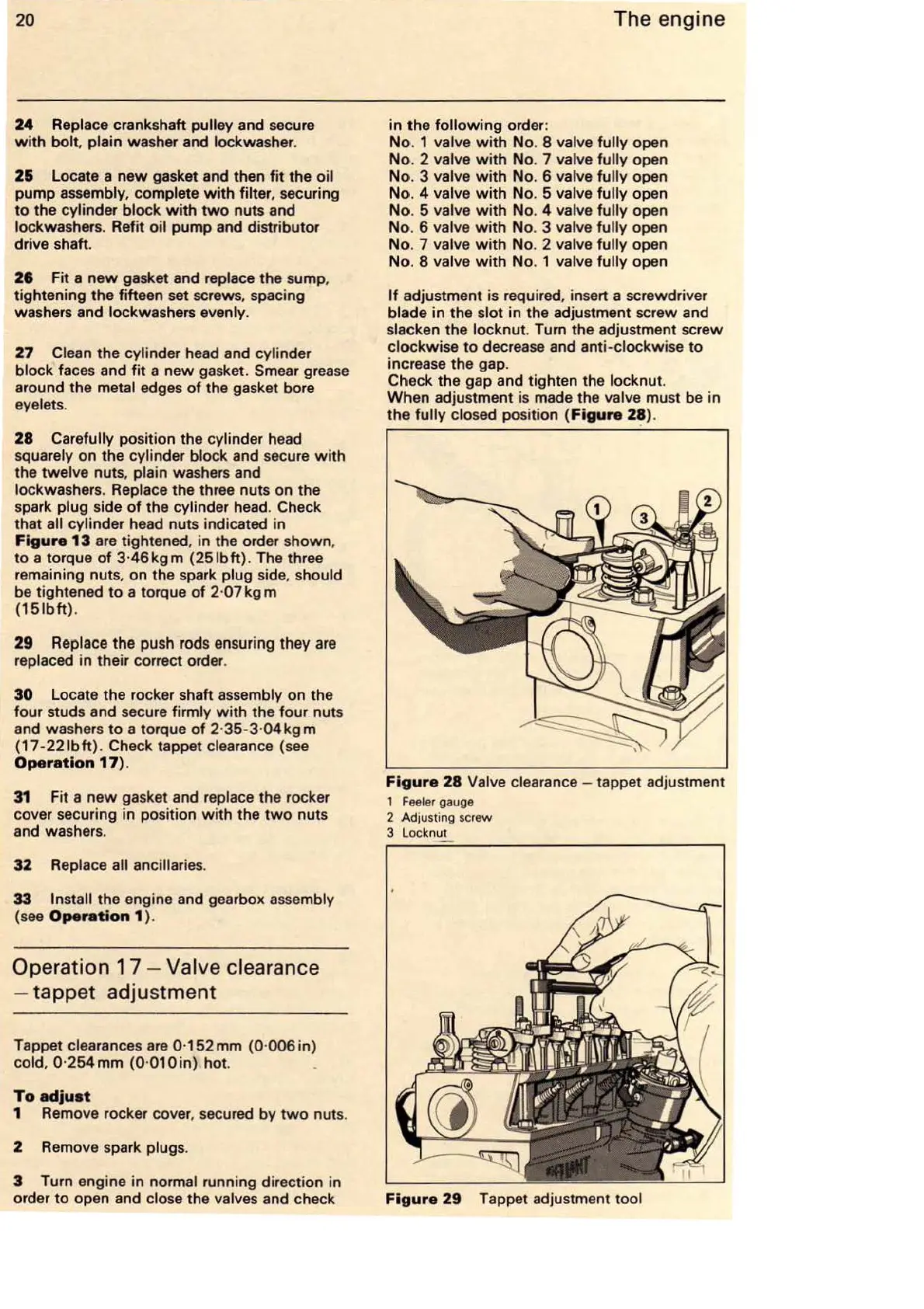
If
adjustment is required, insert a screwdriver
blade
in
the slot in the adjustment screw and
slacken the locknut. Tum the adjustment screw
clockwise
to
decrease and anti-clockwise
to
increase the gap.
Check the gap and tighten the locknut.
When adjustment
is
made the valve must be in
the
fully
closed position
(Figure
2~
).
Figure
28
Valve clearance - tappet adjustment
1
Feeler
gauge
2 Adjusting screw
3 Locknut
Figure
29
Tappet adjustment tool