Robin 8&0
Workshop
Manuel
Supplement
The engine
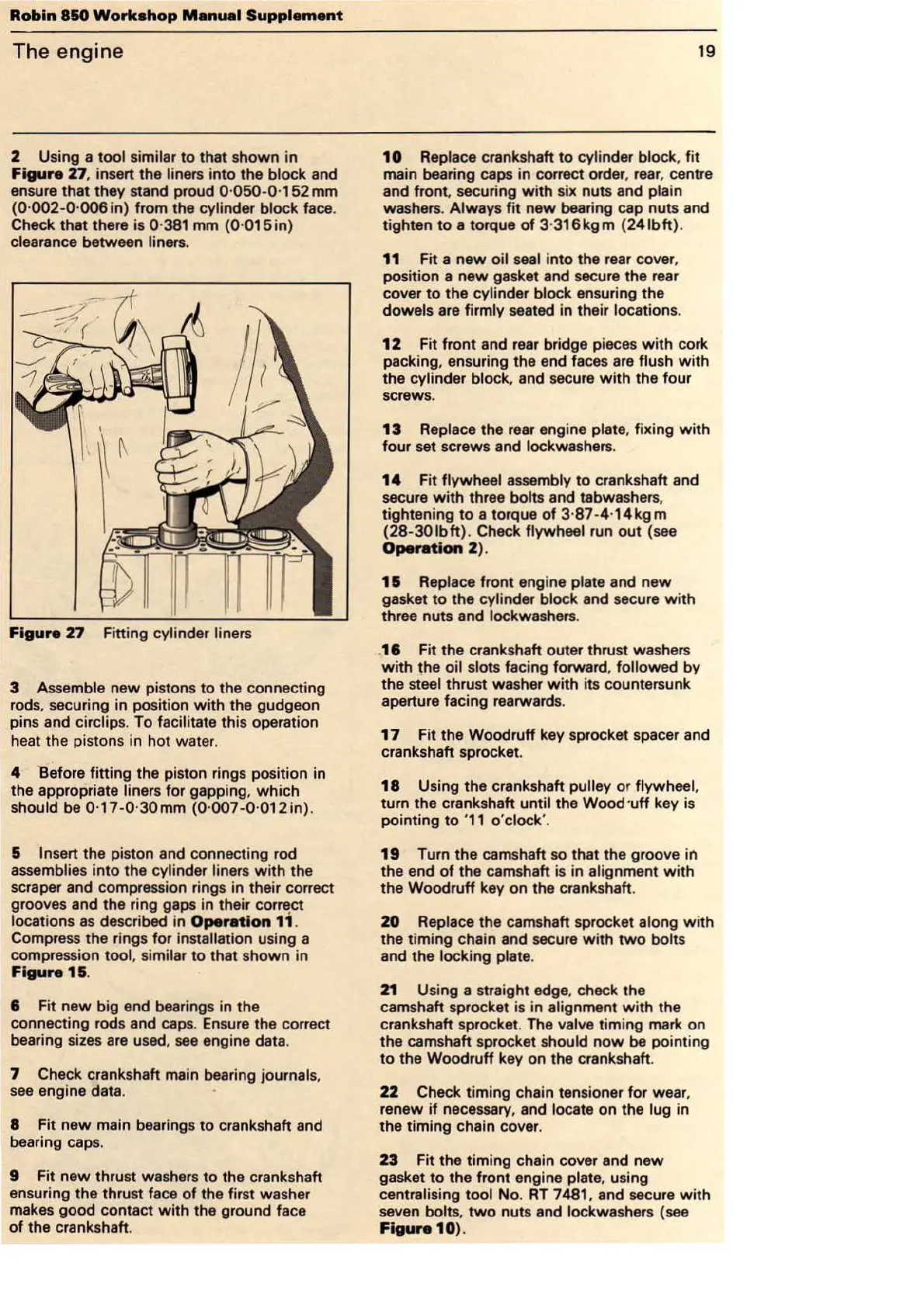
2 Using a
tool
similar
to
that shown
in
Figure
27
, insert the liners into the block and
ensure that they stand proud 0·
050
-0·
152
mm
(0·002-0·
006
in) from the cylinder block face.
Check that there is 0·
381
mm
(0
·
015in)
clearance between liners.
Figure
27
Fitting cylinder liners
3 Assemble new pistons
to
the connecting
rods. securing in position
with
the gudgeon
pins and circlips. To facilitate this operation
heat the pistons in hot water.
4 'Before fitting
the
piston rings position in
the appropriate liners for gapping. which
should be 0·17
-0·3
0mm
(0
·
007-0
·
012in)
.
& In
se
rt the pis
ton
and connecting rod
assemblies into the cylinder liners with the
scraper and compression rings in their correct
grooves and the ring gaps in their
corn~ct
locations
as
described in Operation
11
.
Compress the rings for installation using a
compression tool. similar
to
that shown in
Figure
1&
.
6 Fit
new
big end bearings in the
connecting rods and caps. Ensure the correct
bearing
sizes
are
used,
see
engine data.
7 Check crankshaft main bearing journals,
see
engine data.
8 Fit
new
main bearings
to
crankshaft and
bearing caps.
9 Fit new thrust washers
to
the crankshaft
ensuring the thrust face
of
the first washer
makes good contact with the ground face
of
the crankshaft.
19
10
Replace crankshaft
to
cylinder block, fit
main bearing caps in correct order, rear, centre
and
front
, securing
with
six nuts and plain
washers. Always
fit
new
bearing cap
nu
ts and
tighten
to
a torque
of
3·
316kgm
(241bft).
11
Fit a
new
oil seal into the rear cover,
position a
new
gasket and secure the rear
cover
to
the
cylinder block ensuring the
dowels are firmly seated in their locations.
12
Fit front and rear bridge pieces
with
cork
packing, ensuring the end faces
are
flush
with
the cylinder block, and secure
with
the four
screws.
13
Replace the rear engine plate, fixing
with
four set screws and lockwashers.
14
F
it
flywheel assembly
to
crankshaft and
secure
with
three bolts and tabwashers,
tightening
to
a torque
of
3·
87
-4·
14kgm
(28-301bft). Check flywheel run
out
(see
Operation
2)
.
15
Replace fr
ont
engine plate and new
gasket
to
the cylinder block and secu
re
with
three nuts and lockwashers.
.
16
Fit the crankshaft outer thrust washers
with
the oil slots facing forward, followed by
the steel thrust washer
with
its countersunk
aperture facing rearwards.
17
Fit the Woodruff key sprocket spacer and
crankshaft sprocket.
18 Using the crankshaft pulley or flywheel,
turn the crankshaft until the Wood ·
uff
key is
pointing
to
'
11
o'clock'.
19
Turn the camshaft so that the groove in
the end
of
the camshaft is in alignment w
it
h
the Woodruff key on the crankshaft.
20
Replace the camshaft sprocket along
with
the timing chain and secure w ith
two
bolts
and the locking plate.
21
Using a straight edge, check the
camshaft sprocket is in alignment with the
crankshaft sprocket. The valve timing mark on
the camshaft sprocket should
now
be pointing
to
the Woodruff key
on
the crankshaft.
22
Check timing chain tensioner for wear,
renew
if
necessary, and locate on the lug in
the timing chain cover.
23
Fit the timing chain cover and new
gasket
to
the front engine plate, using
centralising tool
No
.
RT
7481 , and secure with
seven bolts,
two
nuts and lockwashers (see
Figure
10)
.