The gearbox Section G
13
Repeat operation
for
two
remaining balls.
14
Slide 3r
d/4th
synchro sleeve along synchro
body until
it
clicks
into
position.
Note:
Ensure the sleeve is
not
pushed too far,
otherwise the synchro
balls and thrust blocks
will
be
disturbed.
15
Reposition mainshaft in vice
or
assembly
pot
to facilitate
1st/2nd
synchro
body
assembly.
16
Fit springs and plungers to synchro body.
17
Slide
1st/2nd
synchro sleeve over synchro
body
leaving sufficient room to enable fitment
of
thrust blocks and balls. Ensure the teeth
of
the synchro sleeve are facing forward.
18
Fit the three thrust blocks, leaving synchro
ball seatings completely visible.
19
Seat synchro
body
ball in thrust block,
press
ball
down
onto
plunger and slide thrust
block between sleeve and synchro
body
.
20
Repeat operation
for
two
remaining balls.
21
Position baulk ring on 1st speed gear.
22
Fit 1st speed gear bush into its location in
gear
body
.
23
Apply
'Mo
lygr
ease
799' to gear bush and
then
fit
into
1st gear.
24
Pos
it
ion 1st gear, including bush and baulk
ring,
onto
mainshaft splined end.
25
Rotate 1st gear bush, until
it
fully
locates
in the bush key seated in 1st
/2n
d synchro
body
.
Note
: Handle mainshaft gear cluster
with
care
to
prevent synchro sleeves, etc. from being
disturbed.
Primary gear assembly
To
dismantle
1 Using circlip pliers General Tool N
o.
7066
remove Circlip securing front bearing
to
primary
gear.
2 Remove spacer and front bear
in
g from
primary gear.
3 Withdraw needle
roller bearing from inside
primary gear body. This bearing may have been
removed
with
mainshaft assembly.
4
Inspect front bearing and needle roller
bearing
for
wear, renewing
if
necessary.
5 Replace components in reverse order.
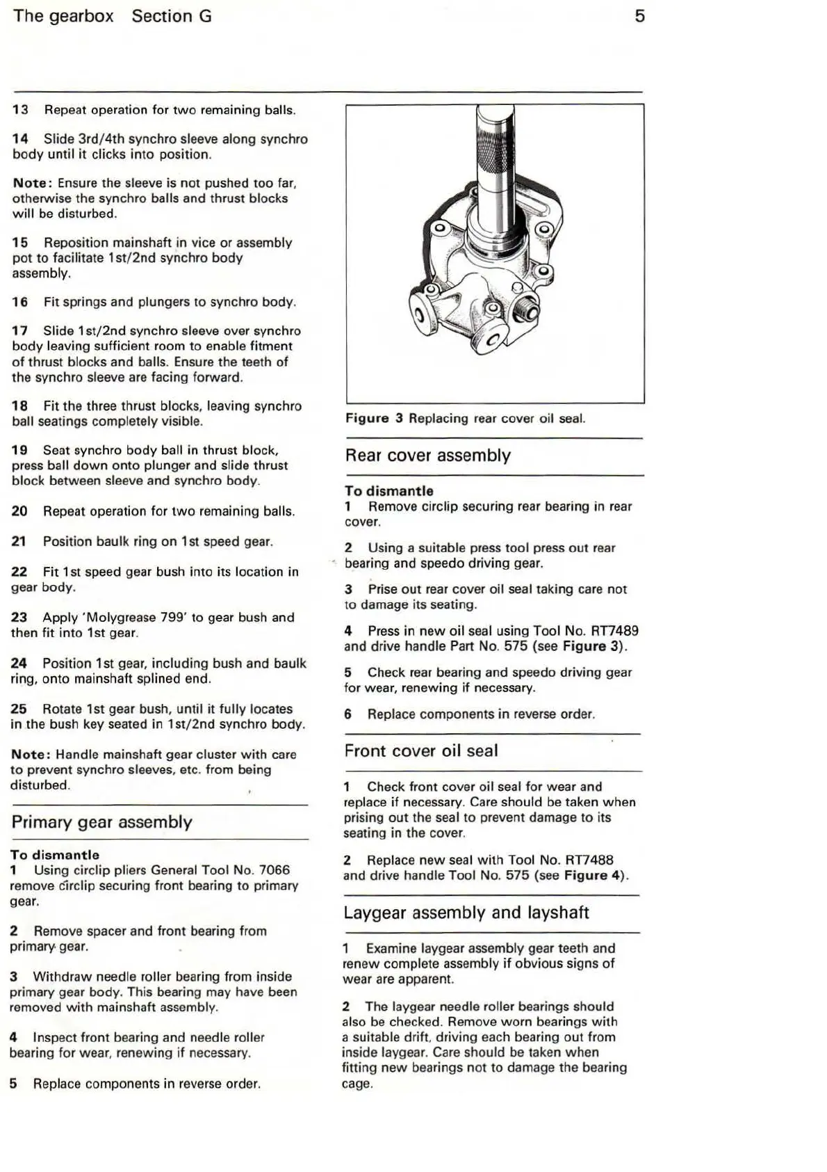
Figure
3 Replacing rear cover
oi
l seal.
Rear
cover assembly
To
dismantle
1 Remove circlip securing rear bearing in rear
cover.
2 Using a suitable press tool press
out
rea
r
bearing and speedo driving gear.
3 Prise
out
rear cover oil seal taking care
not
to damage its seating.
5
4
Press
in
new
oil seal using Tool
No
.
RTI489
and drive handle Part No. 575 (see
Figure
3).
5 Check rear bearing and speedo driving gear
for
wear, renewing
if
necessary.
6 Replace components in reverse order.
Front cover oil seal
1 Check front cover oil seal
for
wear and
replace
if
necessary.
Ca
re
should be taken when
prising
out
the seal
to
prevent damage to its
seating in the cover.
2 Replace new seal
with
Tool No.
RTI488
and
dr
iv
e handle Tool No. 575 (see
Figure
4).
Laygear assembly and layshaft
1 Examine laygear assembly gear teeth and
renew complete assembly
if
obvious signs
of
wear are apparent.
2 The laygear needle
roller bearings should
also
be
checked. Remove
worn
bearings
with
a suitable drift, driving each bearing
out
from
inside laygear. Care should be taken when
fitting
new
bearings n
ot
to
damage the bearing
cage.