The gearbox Section G
Figur
e 4 Replacing fro
nt
cover oil seal.
3 If signs
of
scoring are apparent on the
layshaft, due to
worn
needle roller bearings, it
will
have to
be
replaced.
Rever
se
roller gear assembly and
shaft
1 Check reverse gear teeth and renew
assembly
if
necessary.
2 Drive
out
worn bushes
with
a suitable drift
and
fit
n
ew
ones ensuring the e
nd
faces
of
the
bushes are
flush
with
the gear faces.
3
Check reve
rse
gear shaft for scoring and
replace
if
nec
essa
ry.
To
re
assemble
th
e gearbox
1 Re
fit
reverse
idl
er
gear and shaft into gearbox
case
,
with
shaft selector groove to the rear.
2 Position
lay gear assembly
with
its th
ru
st
washer in b
ase
of gearbox.
3 Refit primary gear assembly
into
bell
housing location.
Not
e:
Drive carefully
into
position until
bearing retaining ring is flush
with
case.
4 Feed in mainshaft assembly, taking
ca
re
not
to dislodge synchro thrust blocks and balls. ·
5 Replace rear cover
with
its gasket to
within
6·35mm
(0
·25in)
of
the gearbox face to allow
rotary movement and facilitate positioning
of
layshaft.
6 Turn gearbox on its
top
face and feed
layshaft through thrust washer into laygear
assembly
unt
il
it
mates with its bore in rear end
of
box.
Note
: Tang end on layshaft must
be
at front.
6
7 Position tang
of
reverse shaft to engage
with
horizontal slot in rear cover, and force rear
cover
fully
home.
8 Locate rear suppon mounting, and eanhing
strap
to
rear cover and then secure rear cover
with six
1 UNC set screws and lockwasher
s.
9 Replace coupling flange on mainshaft
spline,
fit
washer and tab washer, a
nd
secure
with
i UNF nut, tightening to a torque
of
6·92kg m (501b ft). Be
nd
over tab washer
to
lock coupling flange
nut
.
10
Replace reverse, 1s
t/2
nd
and 3rd/ 4th
select
or
forks.
11
Replace the
two
interlocking balls in the
cross
drilling bell housing, locating in position
with grease.
12
Line
up
reverse selector shaft in
se
lector
fork
and drive home mills retaining pins.
13
Ensuring
in
terlock pin is
in
position,
replace 1st/ 2nd selector shaft
into
se
lector fork
and lever. Secure in position
with
mills pins.
14
Replace
3rd/4th
selector shaft into mating
fork and
lever, again retaining in position
with
mills pins.
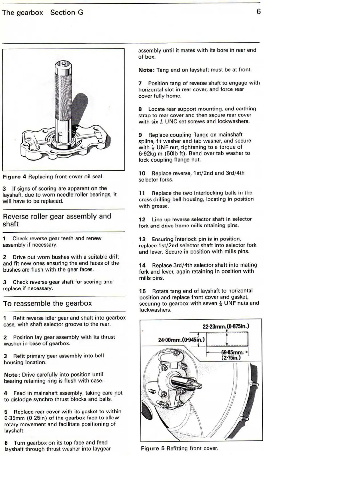
15
Rotate tang e
nd
of
layshaft to horizontal
position and replace front cover and gasket,
securing to gearbox
with
seven 1 UNF nuts and
lockwasher
s.
Figure
5 Refitting front cover.