The clutch Section H
4 Hook brake pedal return spring over pedal
lever and in mounting bracket location.
To
r
eplace
pedal
asse
mbly
1 Manoeuvre pedal assembly to clear steering
column and position on body mounting.
Ensure L.H.
weld
bolt
locates
in
brake master
cylinder bracket.
2
Secure pedal assembly to body and master
cylinder
with
two
-h UNF set screws.
two
-h UNF nuts, lockwashers and plain washers.
3 From inside
footwall insert clevis pin and
connect master
cylinder clevis to brake pedal.
4 Reconnect brake light switch leads.
5 From the engine compartment, through
access aperture,
fit
washer and
new
split pin
to
secure master cylinder clevis
to
brake pedal
lever. Replace rubber grommet.
6 Reconnect accelerator cable lug to pedal
and press in plastic grommet.
7 Locate clutch cable clevis to pedal,
fit
clevis
pin and washer and secure with a new split pin.
Clutch cable
Removal
a
nd
replacement
1 Pull back the clutch cable, unscrew cable
adjuster and
withdraw
cable from cable adjuster
trunnion located in operating lever.
2
From
inside vehicle footwall remove split
pin and washer,
withdraw
clevis pin and
disconnect clutch cable clevis from clutch pedal
lever.
3 Using a 5·56mm ( -/2in) dia. drill, drill the
heads
off
the
two
rivets securing clutch cable
abutment bracket to underside
of
the footwell.
4 Tap out the rivets and
withdraw
cable,
complete
with
abutment bracket from the
vehicle.
Note
: The abutment bracket is press fitted onto
the nylon bush
of
the clutch cable and should
not be removed.
5 When fitting a new
clutch cable assembly,
which
includes the abutment bracket,
two
methods
of
securing the bracket
to
the footwall
can be adopted: (a) rivetting the abutment
bracket to the
footwall,
as
in production or
(b)
drilling out the fixing holes in the bracket
and securing it
with
two
No. 1 0 set
sc
rews,
nuts and lockwashers.
If
the fixing holes in the
footwall body have been enlarged excessively
it is advisable
to
use method (b).
6 Clean
all traces
of
sealing compound from
abutment bracket mounting under
footwall.
4
7 Smear a coating of 'I
CI
Silcoset 152' sealing
compound on the seating face
of
the
new
clutch
cable abutment bracket.
8 Push clevis end
of
new
clutch cable
as
.sembly
through
footwell, locate abutment bracket and
secure
to
body using method (a)
or
(b)
as
previously described.
9 From inside
vehicle footwell connect clutch
cable clevis to pedal lever
with
clevis pin, plain
washer and
new
split pin.
10
Insert threaded end
of
cable through
adjuster trunnion at clutch operating lever and
fit adjuster
nut
.
Clutch adjustment
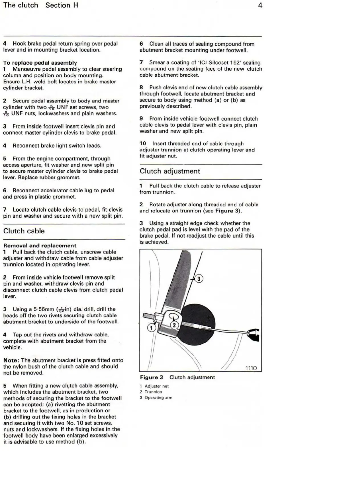
1 Pull back the clutch cable to release adjuster
from trunnion.
2 Rotate adjuster along threaded end of cable
and relocate on trunnion (see
Figure
3).
3 Using a straight edge check whether the
clutch pedal pad is level
with
the pad
of
the
brake pedal.
If
not readjust the cable until this
is achieved.
Figure
3 Clutch adjustment
1 Adjuster
nut
2 Trunnion
3 Operating
arm