The clutch Section H
Figure
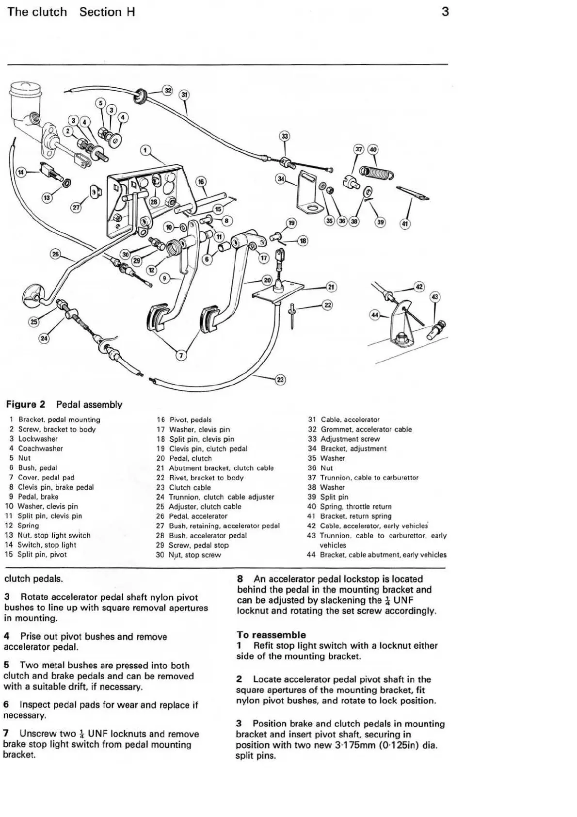
2 Pedal
assem
bly
Bracket. pedal mounting
2 Screw. bracket to body
3 Lockwasher
4 Coachwasher
5
Nut
6 Bush. pedal
7
Cover. pedal pad
8
Clevis pin. brake pedal
9 Pedal. brake
10
Washer. clevis pin
11
Split pin. clevis pin
12
Spring
16 Pivot. p
eda
ls
17 Washer. clevis
pin
18 Split pin. clevis pin
19
Clevis pin. clutch pedal
20 Pedal. clutch
21
Abutment bracket, clutch cable
22 Rivet. bracket to body
23
Clutch cable
24 Trunnion. clutch cable adjuster
25 Adjuster. clutch cable
26 Pedal. accelerator
31
Cable. accelerator
32 Grommet. accelerator
cable
33
Adjustment screw
34
Bra
cket .. adjustment
35 Washer
36
Nut
37
Trunnion. cable to
ca
rb
urettor
38 Washer
39
Split pin
40
Spring. throttle return
41 Bracket. return spring
42
Cable. accelerator. early vehicles
3
13 Nut. stop light switch
14
Switch. stop light
27
Bush. retaining. accelerator pedal
28 Bush. accelerator
ped
al
29
Screw. pedal stop
43 Trunnion. cable to carburetto
r.
early
vehicles
15
Split pin. pivot
30
N9t. stop screw
clutch pedals.
3 Rotate accelerator
pedal shaft nylon piv
ot
bushes
to
line up
with
sq
uare removal apertures
in mounting.
4
Prise
out pivot bushes and remove
accelerator pedal.
5 T
wo
metal bushes are pressed into both
clutch and brake pedals and can
be
removed
with a
suitable drift,
if
necessary.
6
Inspect pedal pads for w
ea
r and replace
if
necessary.
7 Unscrew
two
1 UNF locknuts and remove
brake stop light switch from pedal mounting
bra
cket.
44 Bracket. cable abutment. early vehicles
8 An accelerator pedal lockstep
is
located
behind the
pedal in the mounting bracket and
can
be
adjusted
by
slackening the 1 UNF
locknut and rotating the set screw accordingly.
To
reassemble
1 Refit stop light switch with a locknut either
side
of
the mounting bracket.
2 Locate accelerator pedal pivot shaft in the
square apertures of the mounting bracket,
fit
nylon pivot bushes, and rotate to lock position.
3 Position brake and clutch pedals in mounting
bracket and insert pivot shaft, securing in
position
with
two
new 3·175mm (0·125in) dia.
split pins.