RL78/G13 CHAPTER 11 A/D CONVERTER
R01UH0146EJ0100 Rev.1.00 483
Sep 22, 2011
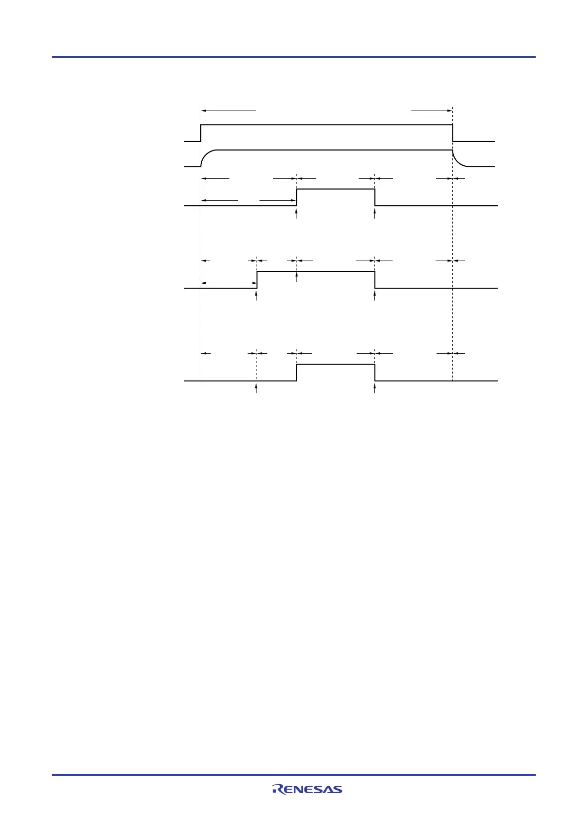
Figure 11-4. Timing Chart When A/D Voltage Comparator Is Used
ADCE
A/D voltage comparator
Software
trigger mode
ADCS
Conversion
stopped
Conversion
standby
1 is written
to ADCS.
0 is written
to ADCS.
Conversion
standby
A/D voltage comparator: enables operation
Note
Note
Hardware trigger
no-wait mode
Conversion
operation
ADCS
Conversion
stopped
Conversion
standby
Trigger
standby
1 is written
to ADCS.
Hardware
trigger detection
0 is written
to ADCS.
Conversion
standby
Conversion
operation
Hardware trigger
wait mode
ADCS
Conversion
stopped
Conversion
standby
Stabilization
wait time
Hardware trigger
detection
0 is written
to ADCS.
Conversion
standby
Conversion
operation
Note While in the software trigger mode or hardware trigger no-wait mode, the time from the rising of the ADCE bit to
the falling of the ADCS bit must be 1
μ
s or longer to stabilize the internal circuit.
Cautions 1. If using the hardware trigger wait mode, setting the ADCS bit to 1 is prohibited (but the bit is
automatically switched to 1 when the hardware trigger signal is detected). However, it is possible
to clear the ADCS bit to 0 to specify the A/D conversion standby status.
2. While in the one-shot conversion mode of the hardware trigger no-wait mode, the ADCS flag is
not automatically cleared to 0 when A/D conversion ends. Instead, 1 is retained.
3 Only rewrite the value of the ADCE bit when ADCS = 0 (while in the conversion
stopped/conversion standby status).

 Loading...


