DURADRIVE Drive Controllers DURADRIVE HDC01.1 Drive Controller 4-71
DOK-DURADR-HDC01.1****-PR02-EN-P
Signal Specification
+5V
Repeater supply
+5V (±10%)
max. 75 mA
Repeater control signal TTL compatible 1: transmit
0: receive
Output resistance: 350 R
V
OL
<= 0.8 V at I
OL
<= 2 mA
V
OH
>= 3.5 V at I
OH
<= 1 mA
Receive/send data EIA-RS-485 standard
Fig. 4-130: Signal specification
CAUTION
Danger of destroying output
"+5V Repeater supply" with overload!
⇒ do not short
⇒ do not exceed maximum current
The definition of the displays are in the firmware functional description.
Bus Connector
Fa5127f1.fh7
1)
H30
H31
H32
H33
H30
H31
H32
H33
PLC control
PROFIBUS-DP
first
drive controller
Matching resistor
at the start of the
PROFIBUS line
must be set on ON
Matching resistor at
the beginning of the
PROFIBUS line must
be set to ON
1) Set matching resistor
to OFF
last
drive controller
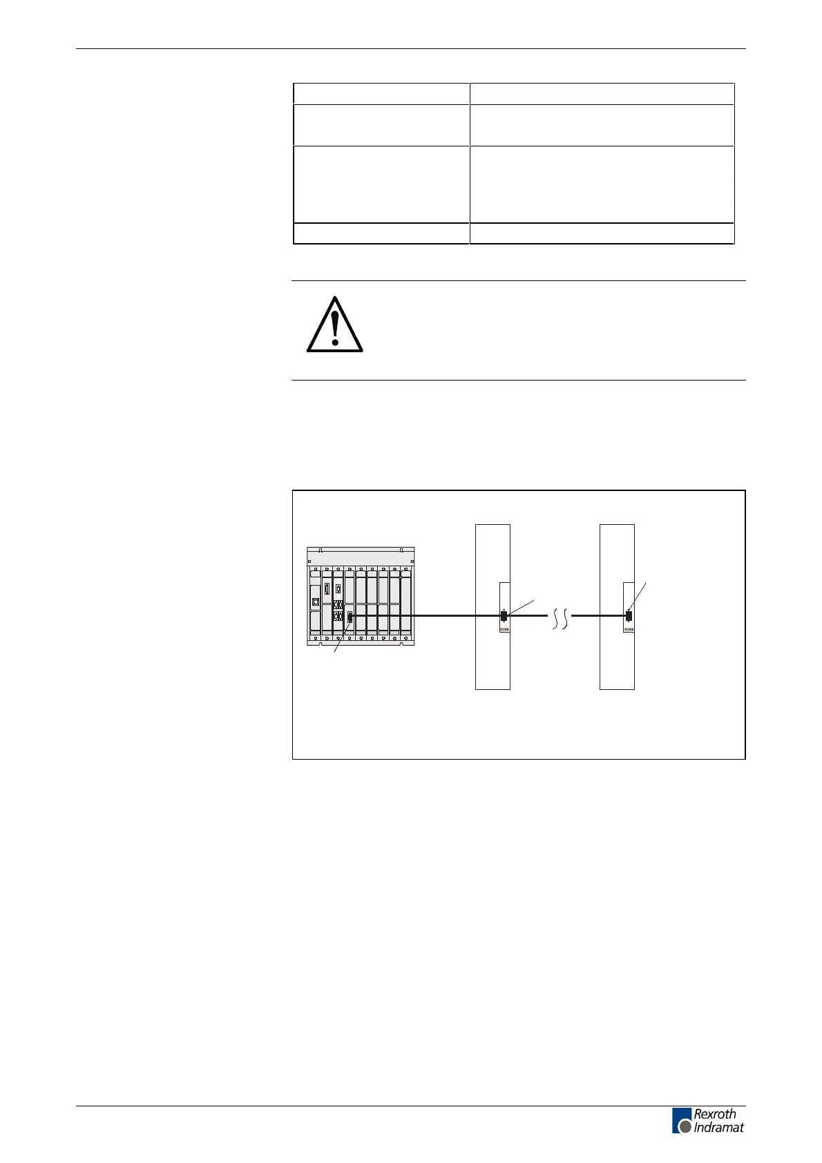
Fig. 4-131: An example of connecting a drive controller to the PLC control via
the PROFIBUS-DP
The PROFIBUS connectors each have a connectable terminating
resistor. The terminating resistor must always be active at both the first
and last bus stations. Do not interchange the A and B wires. Perform the
connection as shown in the figures below.
Signal specification
Diagnostic display
H30 – H33
LSA Control S.L. www.lsa-control.com comercial@lsa-control.com (+34) 960 62 43 01



 To Next Page