DURADRIVE Drive Controllers Constructing the control cabinet 8-1
DOK-DURADR-HDC01.1****-PR02-EN-P
8 Constructing the control cabinet
8.1 Power dissipation
Power dissipation is determined by the current load and the regenerated
power. The actual generated power dissipation depends on the relevant
load cycle, which is limited by the servo motor being used.
On the average, the maximum continuous standstill current I
dN of the
motor flows through the drive controller
⇒ Look up in the relevant motor document both the continuous standstill
current I
dN
and torque M
dN
.
⇒ Determine rms torque M
eff
of the application (see motor document).
⇒ Determine the following relationship current I
dN
effdN
M
M*I
I =
Fig. 8-1: Determining current I
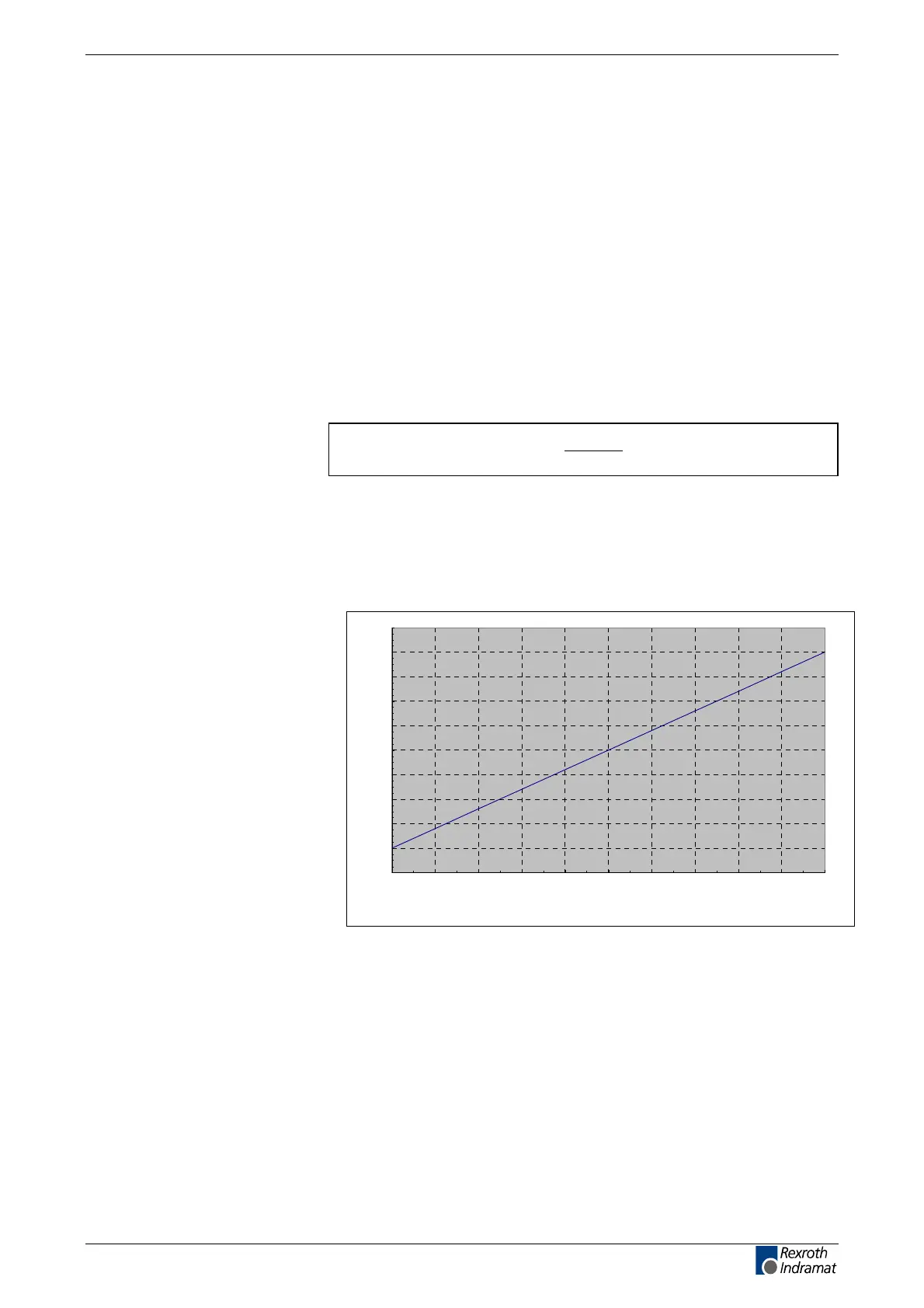
⇒ Using current I, find the corresponding value of the current-dependent
power dissipation P
V,HDC, using the diagrams "Determining Power
Dissipation in the control cabinet".
⇒ Add both power losses (P
V,HDC and PV,Bleeder).
0
20
40
60
80
100
120
140
160
180
200
0
0
0,5
1
1
2
1,5
3
2
4
2,5
5
3
6
3,5
7
4
8
4,5
9
5 (8 kHz)
10 (4 kHz)
I [A]
Pv [W]
P
V
: Power dissipation
I: Current (sine peak value)
Fig. 8-2: Determining power dissipation in the control cabinet for each drive
controller HDC01.1-A040N (ventilated) with 4 kHz and 8 kHz
Determining power dissipation
HDC01.1-A040N (not ventilated):
4 kHz and 8kHz
LSA Control S.L. www.lsa-control.com comercial@lsa-control.com (+34) 960 62 43 01