1-6 Introduction to the system DURADRIVE Drive Controllers
DOK-DURADR-HDC01.1****-PR02-EN-P
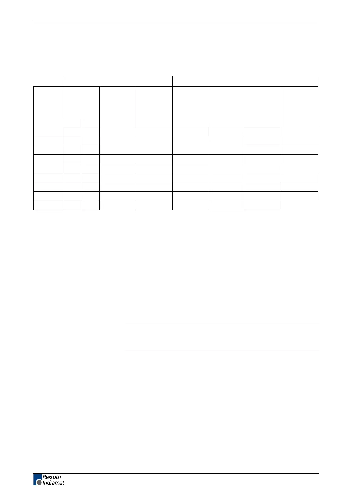
An overview of measuring systems supported
Connecting the systems to the encoder inputs
Encoder 1 (plug X4) Encoder 2 (plug X8)
Digital
servo-
feedback
(1)
Type of
motor
DSF HSF
Resolver with
FDS
(2)
Resolver
without FDS
(3)
Sine encoder
(4)
EnDat
encoder
(5)
Gear-type
encoder with
1Vss signals
(6)
Square-wave
encoder with
5V TTL signals
(7)
MKD
XX
MKE
XX
MHD
X
2AD
XX X
*)
ADF
XX X
*)
1MB
XX XX
*)
MBW
XX XX
*)
LSF
X
MBS
XXX
Fig. 1-6: Connecting the measuring systems
(1) : single-turn or multi-turn DSF / HSF
(2) : resolver or multi-turn resolver (RSF) with
feedback data storage (FDS)
(3) : resolver or multi-turn resolver (RSF) without
feedback data storage (FDS)
(4) : incremental measuring system with sine signals
(1Vss signals)
(5) : absolute measuring system with EnDat interface
(6) : gear-type encoder with 1Vss signals
(7) : square-wave encoder with 5V TTL signals
-> *) not recommended (due to maximum input frequency
of 200 kHz)!
Note: The cable type designations of the connecting cables required
are listed in the motor project planning manual or "List of
Connecting Cables for DIAX04 and ECODRIVE03".
See also the firmware functional description: "Setting the Measurement
System".
LSA Control S.L. www.lsa-control.com comercial@lsa-control.com (+34) 960 62 43 01