DURADRIVE Drive Controllers DURADRIVE HDC01.1 Drive Controller 4-25
DOK-DURADR-HDC01.1****-PR02-EN-P
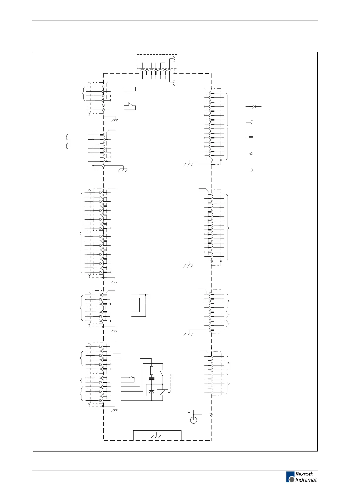
Independent of the drive controller type – total connecting diagram
HDC01.1 drive controller
X4
1
2
(S3)
3
(S4)
4
5
6
8
(SDO)
9
(S1)
10
(S2)
11
7
(SCL)
12
(R1)
13
14
(FS)
(SDI)
encoder 1
1
G2_5VSen
2
G2_0VSen
3
G2Ref-
4
G2Ref+
5
G2Cos-
6
G2Cos+
8
G2Sin-
9
G2EnDatD+
10
0V
11
G2EnDatClk+
7
G2Sin+
12
G2_5V
13
G2EnDatClk-
14
0V
G2EnDatD-
encoder 2
X8
X5
TM+
TM-
BR+
BR-
X13
A1
A2
A3
motor connection
1
2
3
4
5
6
7
clear error
8
warning
9
ready
10
analog E1+
11
Analog E1-
X3
12
analog E2+
13
analog E2-
14
0V
15
analog A1
16
U
D
17
analog A2
18
0V
digital and analog
inputs and outputs
motor temperature monitoring
holding brake
E-Stop
limit+
limit-
AP5357f1.FH7
XS1/XS2/XS3/XS4
mains connection
L1
L2
L3
(*) not present at
the 40A device
ref
cam1 / messT1
cam2 / messT2
(*)
(*)
X11
1
2
3
4
5
6
7
8
9
10
11
12
+24Vpro
0V
0V
2
RxD
RxD
TxD
TxD
RS 232
interface
RS 485
interface
X2
3
4
RS485+
RS485+
5
RS485-
RS485-
7
0V
0V
0V
0V
10
12
+5V
+5V
n.c.
G1Sin+
G1Cos+
0V
n.c.
0V
G1SDAO
G1Sin-
G1Cos-
0V
G1SCLK
G1_8V/Sin
0V
G1Sample
G1SDAI
1) designation from the first ECODRIVE
1)
(R-)
(R+)
(B-)
(B+)
(A+)
(A-)
Bb
Bb
+24V
On1
On3
On2
On4
activation
power on
15
C
B
A
PE
D
E
F
G
H
I
15
A
B
C
D
PE
XE1
not fitted
X10
EcoX-
expansion
interface
1
2
3
4
5
6
IAN+
0V
IAN-
IAN+
IAN-
0V
XS: shield connection
XE: protective conductor
connection
X: clamp pin
designation
spring tension
terminal socket
plug connection
socket
plug connection
pin
screw
connections
electric conduction
to the device
housing
protective conductor connection
(mains) >= 10 mm²
interface for
ZKS control
ready for operation
XS
E
F
G
H
I
X14
123456 7
+UL 0V DZ DK LK LK
cooling fan unit connection
connection for
control voltage
X1
2
+24V
+24V
1
0V
3
4
0V
K1NC
K1NC
5
6
feedback
power contactor
ZKS1
ZKS2
Fig. 4-33: Total connection diagram for HDC01.1
LSA Control S.L. www.lsa-control.com comercial@lsa-control.com (+34) 960 62 43 01

 Loading...