4-6 DURADRIVE HDC01.1 Drive Controller DURADRIVE Drive Controllers
DOK-DURADR-HDC01.1****-PR02-EN-P
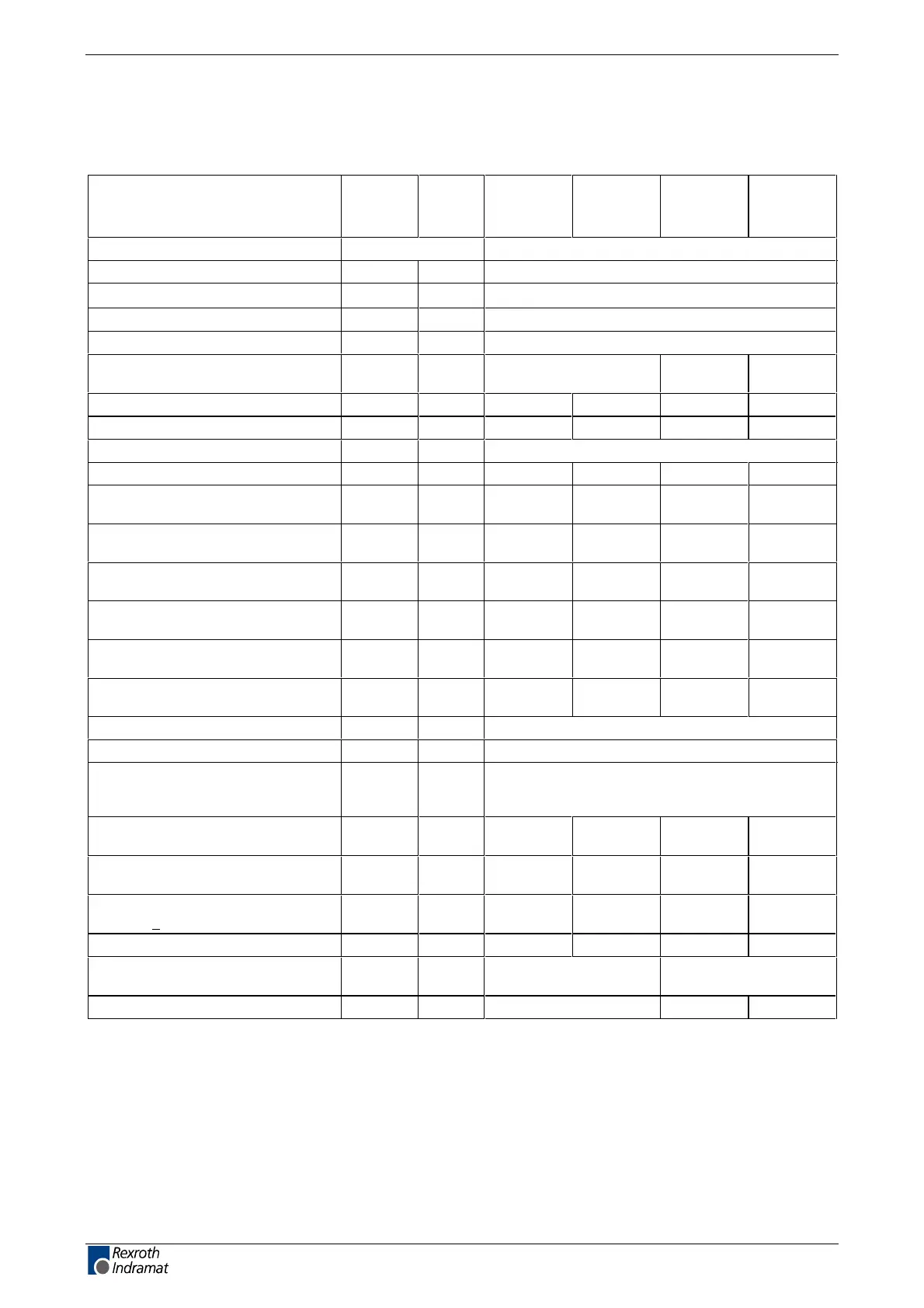
Electric Data of the Individual HDC01.1 Components
Mains connections, Power section HDC01.1-AXXXN
Designation Symbol Unit
40 A
not
ventilated
40 A
ventilated
100 A
ventilated
200 A
ventilated
Operating mode at the mains three phase
Mains input voltage U
N1
V 3 x AC (200 ... 480) ± 10%
Mains frequency f
N1
Hz
(50 ... 60) ± 2
Rotating field clockwise or counter-clockwise
Connected load S
N1
kVA see page 7-1: " Mains Connections"
Nominal charging current
(dependent on mains input voltage)
I
ON
A 5 ... 12 24 ... 56 12 ... 28
soft-start resistor R
Softstart
Ohm60601224
continuous power soft-start resistor P
Softstart
kW 0,075
2)
0,15
2)
0,5
2)
1,5
2)
Switching frequency (selectable) f
S
kHz 4 or 8
Type current = peak current 1 I
PEAK1
A 40
1)
40
1)
100
1)
200
1)
Peak current 2 for f
S
= 4 kHz
I
PEAK2
(4kHz)
A 10
1)
16
1)
40
1)
100
1)
Peak current 2 for f
S
= 8 kHz
I
PEAK2
(8kHz)
A5
1)
12,5
1)
32
1)
68
1)
Continuous current 1 for f
S
= 4 kHz
I
CONT1
(4kHz)
A7,5
1)
13
1)
32
1)
85
1)
Continuous current 2 for f
S
= 4 kHz
I
CONT2
(4kHz)
A 10
1)
16
1)
40
1)
100
1)
Continuous current 1 for f
S
= 8 kHz
I
CONT1
(8kHz)
A3
1)
9
1)
21
1)
48
1)
Continuous current 2 for f
S
= 8 kHz
I
CONT2
(8kHz)
A5
1)
12,5
1)
32
1)
68
1)
Max. Output frequency at f
S
=4 kHz f
out
Hz 400
Max. Output frequency at f
S
=8 kHz f
out
Hz 400
Device power dissipation without
internal continuous bleeder power
for I
CONT2
P
V
W (see page 8-1: "Power dissipation")
Peak bleeder power when
U
ZW
= 830V
P
BS
kW 11,5 11,5 57,4 115
Allowed load cycle
On
Off
0,435 s
66,7 s
0,435 s
33,3 s
0,54 s
62 s
0,52 s
40 s
Continuous bleeder power HDC
when Ta<45°C
P
BD
kW 0,075 0,15 0,5 1,5
Max. energy dissipation W
R,MAX,
kWs 5 5 31 60
Internal DC bus dynamic brake
(ZKS)
not present present
Resistor for ZKS R
ZKS
Ohm not present 12 6
LSA Control S.L. www.lsa-control.com comercial@lsa-control.com (+34) 960 62 43 01

 Loading...