DURADRIVE Drive Controllers DURADRIVE HDC01.1 Drive Controller 4-7
DOK-DURADR-HDC01.1****-PR02-EN-P
Designation Symbol Unit
40 A
not
ventilated
40 A
ventilated
100 A
ventilated
200 A
ventilated
Storable energy of the DC bus
capacitors
W
ZW,
Ws see diagram page 4-14: "Storable energy in the bus"
nominal DC bus capacitance HDC C
ZW
mF 0,585 2,35 4,7
DC bus voltage
(dependent on mains input voltage)
U
ZW
V DC 300 ... 800
DC bus continuous power
(dependent on mains input voltage)
P
ZWD
see diagram page 4-16 "Allowed DC bus continuous
power"
max. DC bus continuous power
where
U
N1
= 3 x AC 400V, at Ta<45°C
P
ZWD
kW 0,65 1,3 6,0 15,0
max. DC bus continuous power
where
U
N1
= 3 x AC 480V, when Ta<45°C
P
ZWD
kW 0,75 1,5 7,2 18,0
DC bus peak power P
ZWS
see diagram page 4-16
"Allowed DC bus peak power"
Cooling power section and bleeder
resistor
natural
convection
forced convection
Fig. 4-6: Technical Data Mains connection and Power section
1)
Sine threshold value
2)
Softstart resistor is used after softstart as bleeder (R
B
).
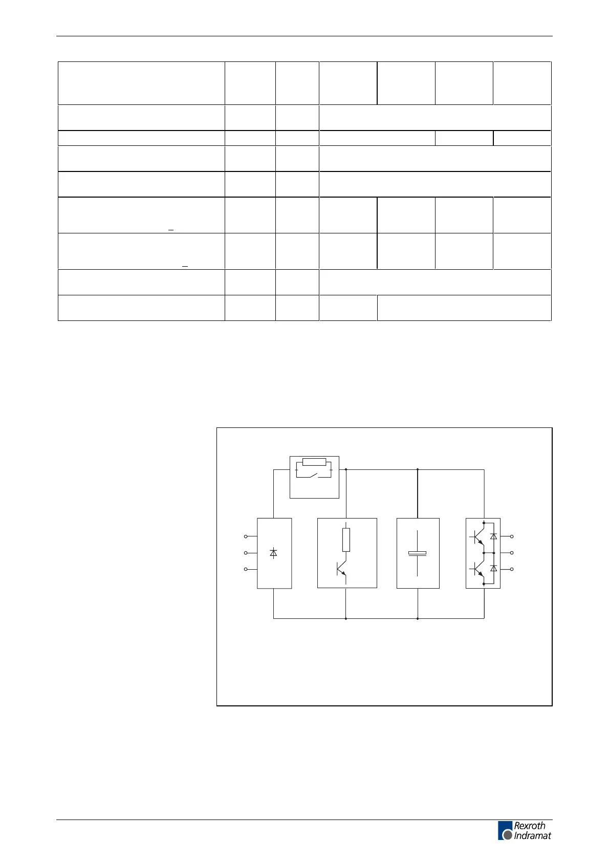
Block diagram of the HDC01.1 power section
R
B
C
ZW
R
soft-start
FS0215F1.FH7
Charging
current limit
A1
A2
A3
L1
L2
L3
Line input
with bridge
circuit
rectifier
Bleeder circuit DC bus
capacitance
Converter
bridge
circuit with
output to
the motor
Fig. 4-7: Block diagram of the HDC01.1 power section
LSA Control S.L. www.lsa-control.com comercial@lsa-control.com (+34) 960 62 43 01
 Loading...
