4-26 DURADRIVE HDC01.1 Drive Controller DURADRIVE Drive Controllers
DOK-DURADR-HDC01.1****-PR02-EN-P
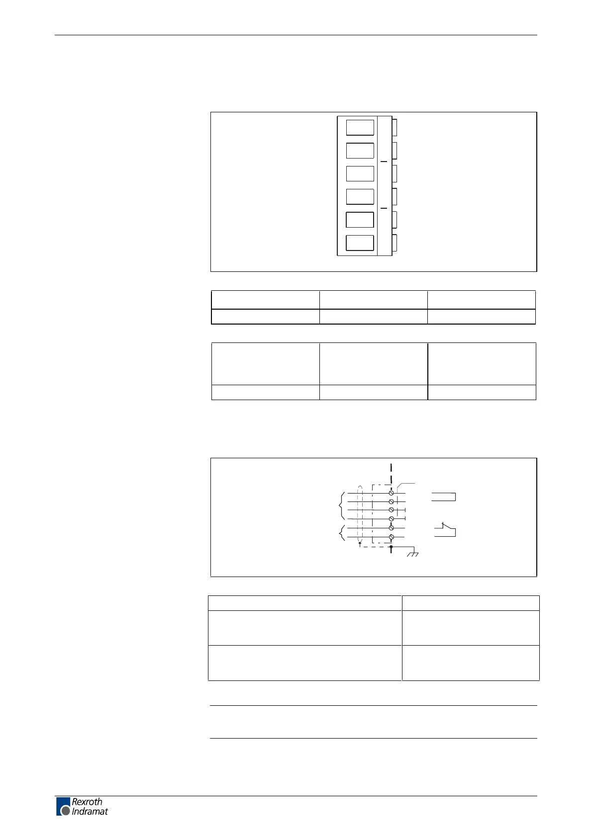
X1, Connections for Control voltage
Technical description of connector
AP5356F1.FH7
+24V0VK1NC
Fig. 4-34: connector X1
Type No. of pins Design
Screw terminal 6 Bushing on connector
Fig. 4-35: Design
Cross section
single wire
[mm²]
Cross section
multi core wire
[mm²]
Cross section
in AWG
Gauge no.:
0,2-4 0,2-4 24-10
Fig. 4-36: Connection cross section
24V control voltage supply (+24V and 0V)
device-external device-internal
AP5358F1.FH7
connection for
control voltage
X1
2
+24V
+24V
1
0V
3
4
0V
K1 NC
K1 NC
XS
5
6
feedback
power contactor
Fig. 4-37: Connections for control voltage
Voltage at X1/+ against X1/-:
DC +24 V (21,6...26,4)
Reverse voltage protection: Via allowed voltage range
using internal protection
diodes
Current or power consumption X1/1: see page 4-8:
"Technical data –> Control
voltage connection for HDC"
Note: Always use a shielded cable for connection. Connect the
shield to XS1, XS2 or XS3.
Illustration
Design
Connection cross section
Connection
+24V and 0V
Connection loads
+24V and 0V
LSA Control S.L. www.lsa-control.com comercial@lsa-control.com (+34) 960 62 43 01