DURADRIVE Drive Controllers DC24V NTM power supplies 5-3
DOK-DURADR-HDC01.1****-PR02-EN-P
FA0200F1.FH7
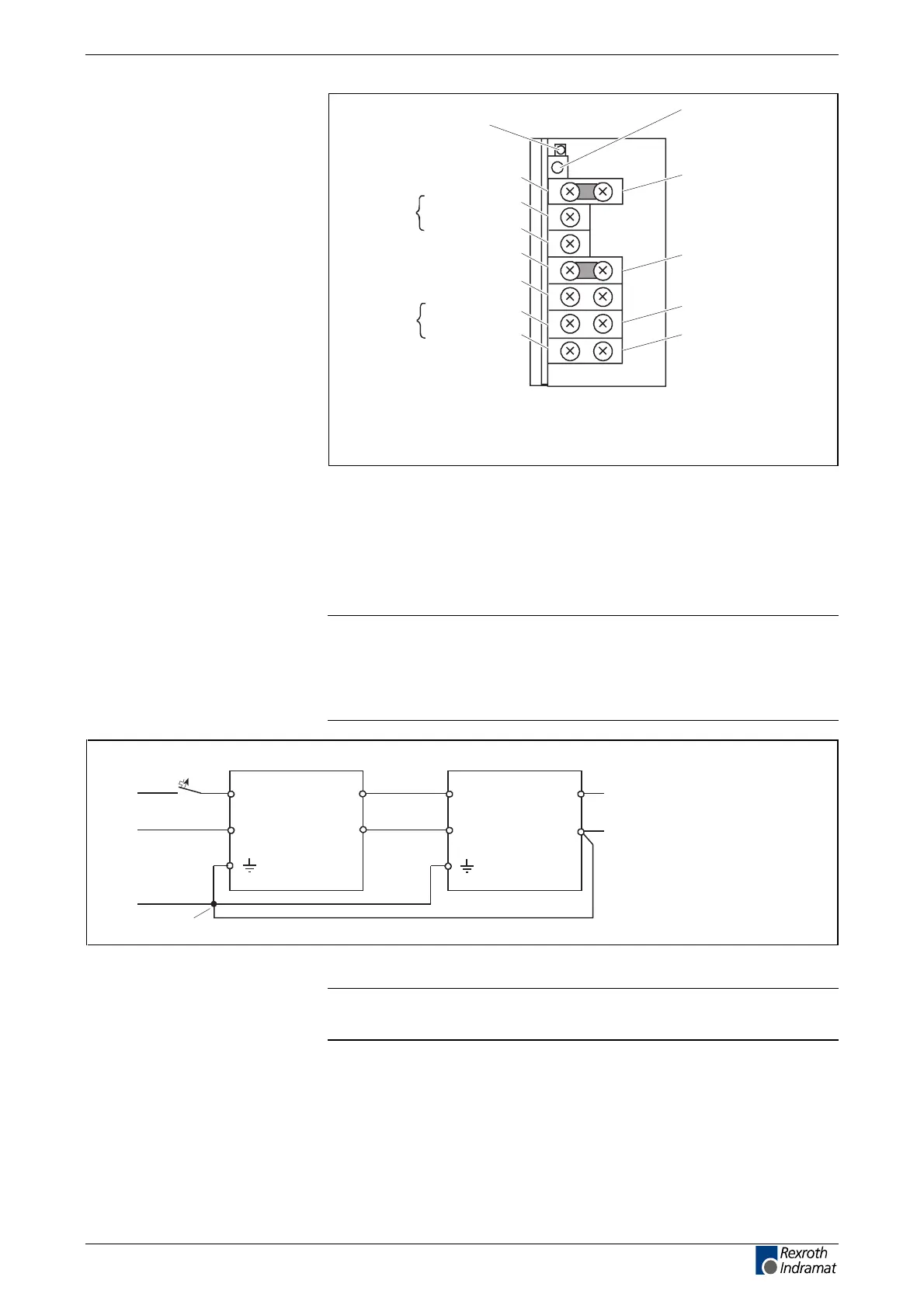
LED green = output
voltage applied
Potentiometer for fine
adjustments of output
voltage
Input
voltage
S+ sensor input
S- sensor input
Input voltage
setting
via bridge
A/B not connected, input voltage AC (170-265) V
A/B connected with bridge, input voltage AC (85-132) V
V+/S+ or V-/S- are connected with bridges
Remove the bridges for using the sensor inputs.
Zero point V-
2)
2)
1)
Output
voltage
Protective ground
V+
V-
FG
L
N
A
B
DC 24 V V+
1)
2)
1)
Fig. 5-4: Front view and terminal designation of the power supplies NTM01.1-
024-004 and NTM01.1-024-006
5.5 Electrical connection
Note: Always use the NTM together with the line filter
NFE01.1-250-006. For further information on NFE, see project
planning manual "Electromagnetic Compatibility (EMC) in
Drive and Control Systems", doc.-type
DOK-GENERL-EMV********-PRxx.
AP0202F1.FH7
NFE ...
L
N
NTM ...
L
N
+DC 24 V
LINE
V+
V-
0 V
Power supplyRF interference suppression filter
PE
LOAD
Q1
central
ground
to the control voltage
connection on the
drive controller
Fig. 5-5: Connecting the power supply to a line filter
Note: The contact bridge between V+/S+ and V-/S- must be
removed if sensor inputs are used.
LSA Control S.L. www.lsa-control.com comercial@lsa-control.com (+34) 960 62 43 01