4-8 DURADRIVE HDC01.1 Drive Controller DURADRIVE Drive Controllers
DOK-DURADR-HDC01.1****-PR02-EN-P
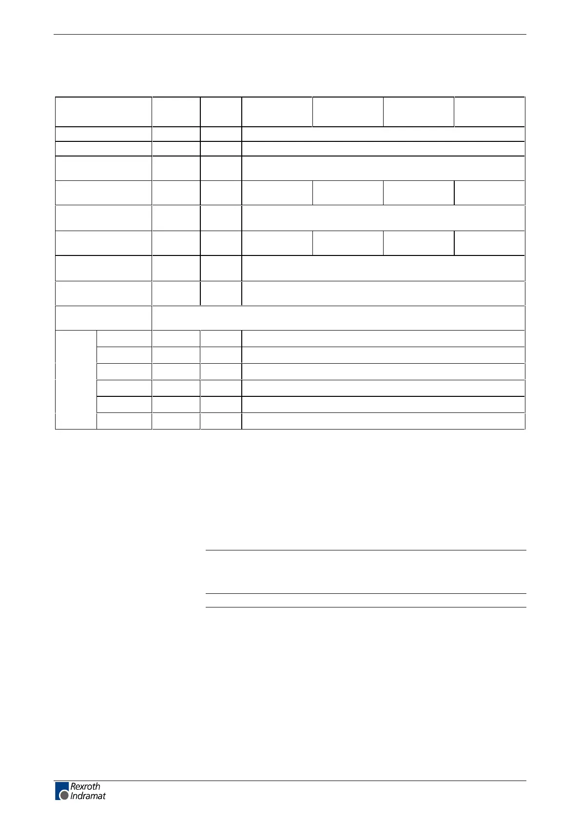
Control voltage connection for HDC
(Data applies to ambient temperature of 25°C)
Designation Symbol Unit 40 A
not ventilated
40 A
ventilated
100 A
ventilated
200 A
ventilated
Control voltage U
N3
V DC (21.6 ... 26.4) V
1)
max. ripple effect w may not exceed input voltage range
max. allowed
overvoltage
U
N3max
V 40 V for 1ms, non repetitive
2)
max. charging
current
I
EIN3
A 6.0 6.0 7.0 7.0
(see diagram "Amplitude of the HDC control voltage charging current
at startup, to selecting power ")
max. pulse duration
of I
EINmax
t
N3Lade
ms 12 12 17 17
(see diagram "Amplitude of the HDC control voltage charging current
at startup, to selecting power "
)
max. input
capacitance
C
N3
mF 0.9 * 1.2
Power input (at X1) dependent on type of unit, without external load at control outputs and
encoder interface 2
CN01 P
N3
W26
DN01 P
N3
W26
IB01 P
N3
W27
PB01 P
N3
W26
SE01 P
N3
W25
SE02 P
N3
W26
Fig. 4-8: Control voltage connection for HDC
1)
For motors with holding brake the minimum voltage required for the
holding brake has to be taken into account (24V ± 10%, measured at
motor).
2)
To be obtained by means of suitable power supply units and separate
wire routing!
Note: The power consumption of the motor holding brake and the
ventilator unit has to be added when computing the control
voltage power.
Note: Overvoltages higher than the 40 V indicated on the data sheet,
have to be discharged by means of the appropriate electrical
equipment of the machine or installation.
This means:
• Use 24 volt power supply units that reduce incoming
overvoltages to the allowed value.
• Install control voltage supply units as close to the drive
controller as possible.
LSA Control S.L. www.lsa-control.com comercial@lsa-control.com (+34) 960 62 43 01
 Loading...
