4-80 DURADRIVE HDC01.1 Drive Controller DURADRIVE Drive Controllers
DOK-DURADR-HDC01.1****-PR02-EN-P
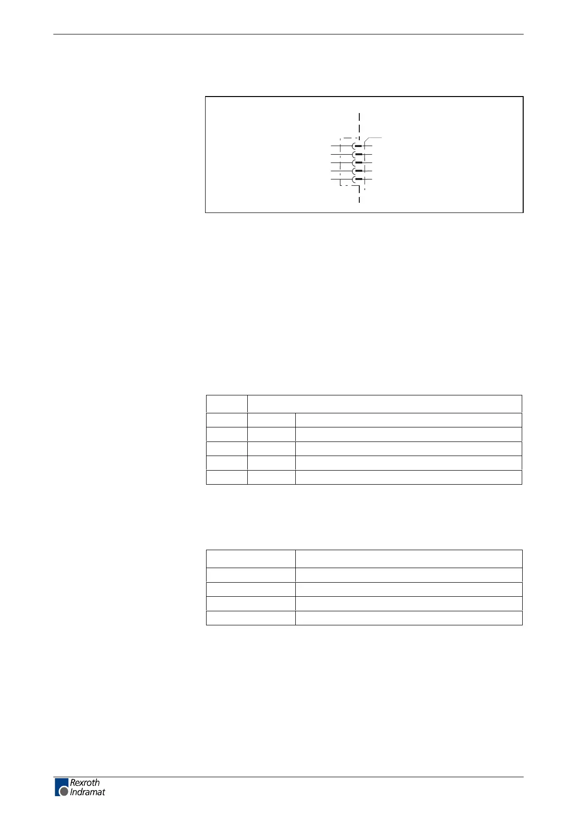
Connection diagram for DeviceNet-Interface
AP5181F1.FH7
DeviceNet interface
X60
1
2
3
4
5
device-external device-internal
V-
CAN-
shield
CAN+
V+
Fig. 4-151: DeviceNet Interface
as per DeviceNet Specification 2.0 Vol. 1
Open Screw Connector
as per DeviceNet Specification 2.0 Vol. 1, Appendix B
as per DeviceNet specification 2.0 Vol. 1, Appendix B
end resistance: 121 Ohm, 1%, ¼ W
as per DeviceNet specification 2.0 Vol. 1,
Pin Definition
1V- 0V
2 CAN- Differential signal
3 shield Shield connection
4 CAN+ Differential signal
5 V+ Interface supply
Fig. 4-152: Interface signal allocation
+30 V
Bus voltage Current feed
11V 70 mA
18 45 mA
24 35 mA
32V 28 mA
Fig. 4-153: Current feed via bus connector
The definition of the diagnostic displays is in the firmware function
description.
Connection
DeviceNet Interface
Interface compatibility
Recommended cable
Bus participant connections
Baudrate and cable length
Plug-in connector assignment
X60
Maximum bus voltage
Current feed at bus
Diagnostic display
H60 – H65
LSA Control S.L. www.lsa-control.com comercial@lsa-control.com (+34) 960 62 43 01



 To Next Page