4-10 DURADRIVE HDC01.1 Drive Controller DURADRIVE Drive Controllers
DOK-DURADR-HDC01.1****-PR02-EN-P
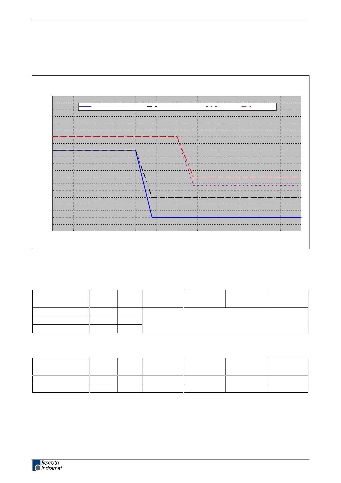
Amplitude of the HDC control voltage charging current at
startup, to selecting power source
charging current
0
1
2
3
4
5
6
7
8
9
10
0 5 10 15 20 25 30
t [ms]
I
EIN3
[A]
HDC040 not ventilated HDC040 ventilated HDC100 HDC200
I
N3
: Current consumption after charging current inrush
Fig. 4-9: Example of charging current inrush of control voltage
Voltage connection for holding brake
Designation Symbol Unit 40 A
not ventilated
40 A
ventilated
100 A
ventilated
200 A
ventilated
Input voltage U
HB
V
max. ripple effect w %
Current I
HB
A
depends on motor type, listed in motor project planning manual
Fig. 4-10: Voltage connection for holding brake
Power consumption of cooling fan units
Cooling fan unit Symbol Unit 40 A
not ventilated
40 A
ventilated
100 A
ventilated
200 A
ventilated
LECH-040N P W - 35 - -
LECH-200N P W - - 45 45
Fig. 4-11: Power consumption of cooling fan units
LSA Control S.L. www.lsa-control.com comercial@lsa-control.com (+34) 960 62 43 01
 Loading...
